I managed to pick up some boot hinges off eBay for only £15 and with these being S&J hinges (same as on my Cobra) they are awesome quality and normally retail at around £85 so that’s a great saving. Fitting these is fairly straightforward and a nice little job to crack on with. I started off setting the boot lid as square on the body as possible then marking lines agains the body on the front, back and both sides. Then I measured off the centre line to the outside edge of each hinge as so they were spaced equally. I played around with the spacing for a bit before settling on eight inches off the centre, as that to me is what looked best. I masked the body and boot with tape and scribed the outline of each hinge which allowed me to mark the drill point for each stud.
I had to use some blue tac to create a spacer between the body lip and underside of the boot in order to sit the boot lid level with the body. I will be fitting a rubber seal trim when all finished to also help with keeping the water out. I have ordered a keyed cam lock to secure the boot and I’m wanting some tan leather boot straps on the back edge also. But none of these have been delivered yet and are not that critical to fitting first, still it will be good to get all the fixing positions marked and drilled prior to prepping all the panel gaps. Once the boot and body were drilled the hinges simply fit on and are secured underside with some penny washers and nuts. I have used some dome nuts on the boot lid as they look nicer when the boot is open, and attention to details is what it’s all about!
Once the boot hinges were sorted I moved onto the wheels. I have had the tyres from the old steel wheels fitted to my recently acquired wire wheels.
I didn’t want to spend money on new tyres yet simply because tyres are date coded nowadays so if this project takes me another two years to finish then I won’t have lost any tyre life during this time. These tyres are in no way safe to use on the road but more importantly they are the correct size so they will allow me to fabricate my metalwork and fit the arches. I need to put a good bit of planning into these arches as I don’t want them to crack or come off when driving any bumpy roads. I specifically want the arches to be spaced off the tyres and to travel with the suspension movement. So this will require fitting to the rear of each hub as opposed to the body itself.
It’s awesome to be able to see how the car will look with the wheels on now, it really makes the car look longer in my opinion, and the twinkle of the red calliper through the front spokes looks tremendous.
So with the wheels also now fitted and the chassis rolling on the wires I was able to continue with the next job, the headlights. I have previously fitted the outer and inner mounting brackets and all I had to do was open up the centre hole to accept the headlight bowl spigot.
I splurged a little with the headlight bowls and went with the stainless steel units as opposed to the chrome on brass. Yes they were three times the price but they do look fantastic and really feel like good quality bits to bolt on. I had previously picked up some 7” headlights on a deal, the same as my Cobra (Lucas style P700) as I really like the look of these lights and I think they look perfect period for what I’m trying to achieve. They simply fit with the large hollow thread shaft and retaining nut from the inside.
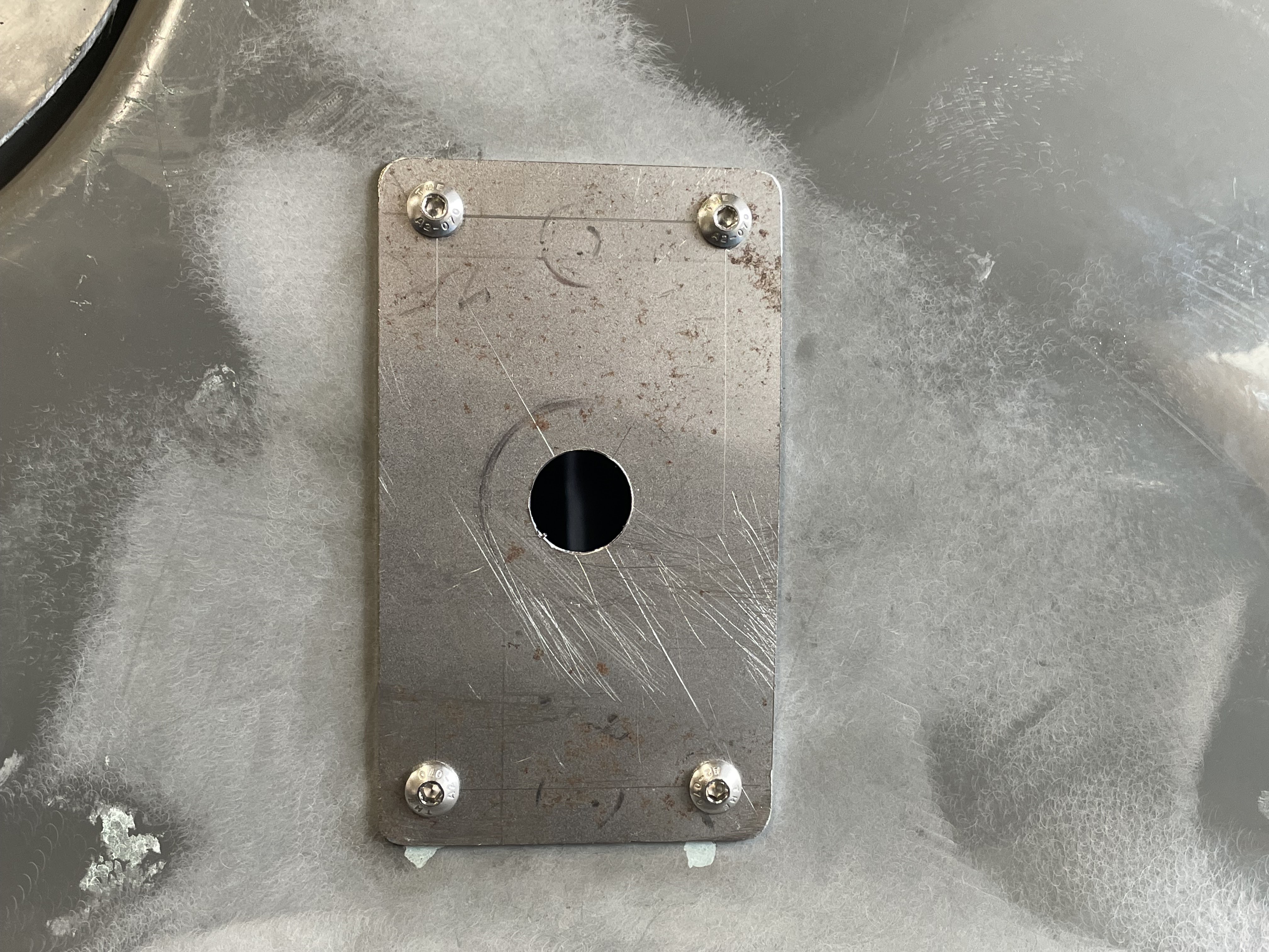
I opened up the centre hole with a step drill slowly until I was able to pass the spigot through and fix easily from inside with the lock washer and nut. Once I had fitted both headlights I was not happy with the overall level of each headlight. The off side sat 50cm from the bottom of the headlight bowl to the floor level and the near side sat at 51cm. I couldn’t drill one of the outer backplates again as it then would not be central and would look odd. I decided to remove the offside rear bracket and fill all the holes in the body before refitting the whole thing again and re making the offside rear bracket again from scratch in order to get the headlights to sit even. You can see in this picture the original holes just showing under the outer bracket. The mistake I made was I simply made both rear bracket’s initially to the same dimensions, just bent opposite for each side. This then dictated the mounting position for the front bracket which in hindsight was way off. Now I have remade the rear bracket which is longer than the near side it allows each outer bracket to sit evenly. Now if I measure from the bottom of the outer plates to the lower body edge they are both sitting at 9cm and thus the centre holes are both level for the headlights.
I refitted the offside headlight and was relieved when I measured to the floor level and both lights are at 51cm and sitting level. This photo shows how they both look, as before I would have been ashamed to picture my bozz eyed attempt at the fitting… it just looked odd. Still all sorted now so I’m able to get on with the next job on the list.
I have managed to pressure up the brakes now and I’m pleased to say all seems well. I’m getting a good feel from the pedal, but I’m hoping for a slight improvement once the pads and shoes are bedded in a little, that will come in time obviously but I have bled the system fully and all brakes are engaging properly. The secondary line was a tad tricky to fit simply because of my cut out box that I had made in the bulkhead for the master cylinder. It only gave me enough space to fit a banjo union (see picture) as I didn’t have the clearance to get a 90 degree bend on the pipe. The banjo seems to have worked well and I have ran the pipe down to a bulkhead fitting by the outer sill. This will run the feed back along the sill to the rear brakes. I have purposely left this brake pipe loose until I have my front dash and steering hoop bar fitted. This is/will be fitted down next to the outer sill so I need to rout the brake pipe around all this once it’s done.
Next job was to tackle the petrol tank install. I have already fitted to two main sections of the boot floor and concluded that the boot floor alone will not support a fuel tank when it’s full and under road vibrations and knocks. My plan was to make a small but sturdy bracket that will fix to the rear bulkhead internal to the boot and then the recess in the tank will allow the full weight to be distributed on that, rather than the boot floor. I made some measurements then set about with some cuts of 6mm angle bar and fairly quickly had welded up a lovely solid bracket.
I spent time cutting the angles correctly and making sure my welds were solid then I added some carpet to the top face as so it wasn’t metal on metal fitting, which would be silly. I also used an old bit of rubber hose split and fitted to the bottom of the tank seam to again help reduce the risk of metal on metal fitting. The back section of boot will also be carpeted to help reduce this risk and help dull any road noise. The bracket seemed to work really well and would certainly take the weight it will be subjected to. I will have to also make some brackets for either end to stop the tank from sliding left to right and hold it securely also. Can’t risk a tank full of fuel breaking free when hitting a road bump or hard corner.
The bracket was easy enough to fit as once I had drilled two bolt holes through it I could just offer it up to the rear bulkhead a scribe through for the drill positions again. This was quickly done and the bracket is going to do a grand job of helping to spread the load of the tank. It really has worked well and should function perfectly. I now need to start making some brackets for either end of the tank to further support and stop any lateral movement when going round corners. I made these from some bits of angled steel that I measured and cut accordingly. I started off making the back brace by crudely measuring the centre points from two of the mounting holes on the fuel tank. I then just increases this by about 5cm overall to give me the length for each back piece.
Then I measured from the tank flange seam to the rear edge of the tank which was roughly 12cm, then added a further 1cm onto this length as I don’t want the tank to physically rub against the rear bulkhead. I made four lengths and welded them to each back plate and finally finished the front face of the bracket with a small plate section in order to bolt the tank through.
After a few trial fits I managed to scribe each bracket where they needed drilling for the fixings. The rear of the brackets will be simply bolt clamped onto the rear bulkhead and I have welded a nut on the backside of each front plate, so the tank can simply be bolted onto the brackets.
I had some carpet already that I have lined the rear bulkhead with and the lower front boot floor, and with the tank back in it was rock solid. I’m extremely happy with how this has all gone and next I will be fitting the rear seat belt supports next which will be a couple of tube sections that run from the bulkhead down to the chassis points in the boot floor. When done will add even further strength to the whole setup and hopefully some safety also. I have to leave space for an electric fuel pump that I’m thinking of mounting on the holes at the top of the tank on the near side. I’m conscious that anything the fuel pump mounts to needs to be isolated for sound transmission…. Nothing worse than driving along listening to the fuel pump.


 I refitted the offside headlight and was relieved when I measured to the floor level and both lights are at 51cm and sitting level. This photo shows how they both look, as before I would have been ashamed to picture my bozz eyed attempt at the fitting… it just looked odd. Still all sorted now so I’m able to get on with the next job on the list.


