Saturday, February 1, 2025

Belt Up And Park Your Seat


So this update is primarily concentrating on the seat belts and the associated fixing bolts. I managed to drop on again on eBay and pick up some suitable four point harnesses which are very similar to the Cobra. I specifically wanted the aero style rotary clasp and black webbing, so being a tad specific I have been keeping my eyes peeled for some time for some to crop up at a reasonable price, and I managed to get a pair for only £50 which is a huge saving than if I purchased them new and direct with Willians. 

The lower two strap fixings are fitted with eye bolts the inner of which utilises the original Spitfire fixing point on the chassis. The outer one is simply drilled through a bracket that was installed when I put the chassis outriggers and out rails on and then the spreader plate is fitted underneath allowing the eye bolt to bolt through from above. I’m going to fit some sound deadening pads to the floor pan sections under the seats, I fear this will be a tad boomy if not. The under seat void is going to be a real bummer for loosing stuff, as I’m fixing both seats without runners, so I might make a little baffle plate to stop stuff rolling around and getting impossible to access because of the seat position. 


Next was to move onto the top fixing positions, which unfortunately I didn’t really photograph or document very well, however I’ll explain my process and you will see from the images how the basic structure was made. 

I started with a length of flat bar steel (3mm) which creates the horizontal and this was cut to length and curved each end to match the body tub. Remember my rear bulkhead is 2mm steel as opposed to plywood so it already has a good tensile strength and I’m just beefing everything up and adding some bracing to help absorb any impact that it might have to deal with. 

Once this was cut I had to define my position for the top two eye bolts. With the seat roughly in position I measured each bolt equally off the centre line of each seat back and at the height that would keep the fixings below the rear seat squab. Then it was easy just to drill a small hole through and marry up with my rear horizontal brace. I specifically made sure that the measurements allowed the fixing holes on the rear brace to be on the horizontal centre line so with the spreader plate behind also giving the most strength to the setup. I simply mirrored my fixings on the offside to the nearside to give me both sides, then I moved onto making the whole thing solid and structural. 
I dug out the pipe bender again (Christmas money well spent a few years ago now) then I had to put a small curve into each support tube in order to clear the petrol tank. 
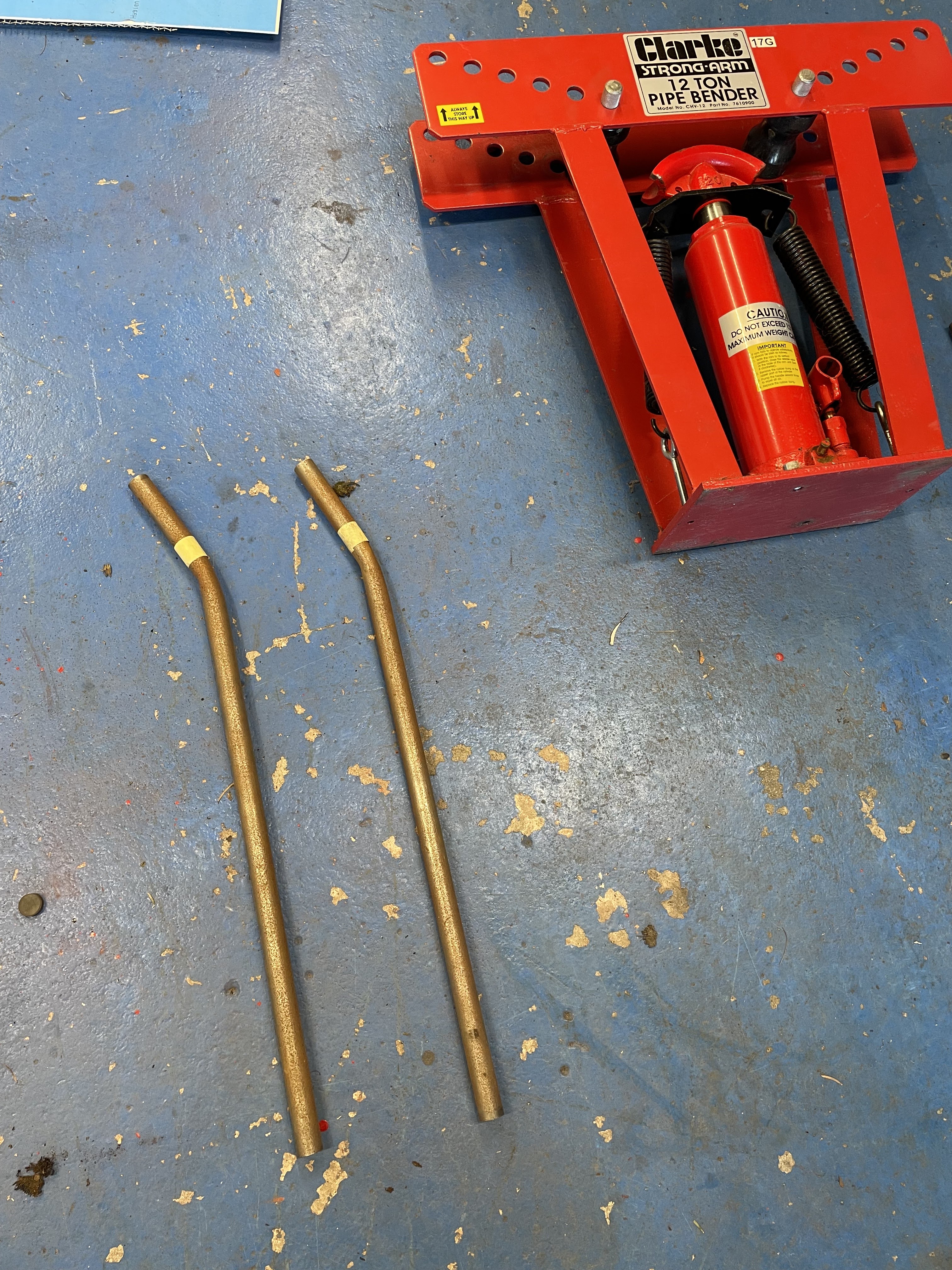

I learnt from last experience to mark each tube equally with masking tape, then by positioning each tube in the same place each time it gave me a fighting chance of making a pair the same. They turned out really well and I was pleased that I only had to put a slight radius on the one end. Triangulation is the strongest form to create strength, but I could use the tubes without a slight kink as they voided on the petrol tank, which is as low as possible already to keep the centre of gravity down. 

With the two tubes bent I was able to cut the mitre into the bottom end and weld it onto a 6mm steel fixing plate, which is then bolted onto the chassis using the original fixing positions on the rear suspension cross brace. The other end of the tub was then tacked to the rear horizontal cross brace I had just made so I was then able to remove the whole rear bracing and beef up all the welds along with tarting it all up with some paint. 

With both braces in place and painted it was really really solid and should be more than sufficient for its purpose. However I hope I should never need to test this functionality…. Better safe than dead haha. 

The next niggle I had was a little knocking where the rear braces bolt down through to the chassis. When I fitted the boot floor I kept everything as low as possible to keep the petrol tank down as mentioned previously. This in turn has allowed the boot floor to rest on the chassis mounts, and despite being bolted through and torque down tight it was still allowing a slight tapping/knocking between the flex of the alloy boot floor and the chassis top mounts when giving it all some movement. I was aware of this issue prior to the seat belt fixing braces, but this has now accentuate it slightly and I was reminded when I was giving it a bloody good wobbling when I fitted them. 
I have solved this problem by unbolting the lower fixing bolts from the newly made bracket which has allowed me to slide some strips of rubber between the chassis mounts and the underside of the boot floor, then when everything has been bolted back down I was able to stand in the boot (on the rear diff) and bounce up and down with no knocking or tapping whatsoever…. Great success!

Next on the list of jobs was to fix the seats into position. The seats have to be secure obviously but not to the same extent as the seat belt fixing braces, still I belt and braces everything I do so I doubt it will be any different for this task. 

I started off with some strips of flat bar steel (4mm) and after offering the seat shell roughly into position I started making some lengths to support the front and back of the seat shell. I have cut the prop shaft cover so that it doesn’t act as a spacer on the one side for the brackets as I’m trying to keep the seats as low as possible and 1-2mm higher on the one side all adds up and would technically not sit the shell flat. Once these strips were cut they have been fixed into the chassis and outer sill but using countersunk machine screws as the seat shell would sit on the bolt heads if using a standard bolt. Again these don’t have to be super strong as such because any force acted upon them is the weight of the seat shell only, the body weight mass is transferred to the harnesses and the seats would stay in position as they have little mass in comparison to a human. 

Next I added two further strips of flat bar steel to give more support for under the seat. I cut them to length and welded them into position so that the seat frame becomes one piece ready for painting. I could then fit the seat into position and really get a flat solid mounting position which felt much more substantial. I made four fixing bolts through the seat shell into the now complete seat frame and secured using some M8 bolts and rivnuts. This will allow me to remove the seats easily should I want or need to later on. 


Now I was able to fix the seats shells and the new harnesses and really get a feel for the driving position overall…. I was very happy to be fair. Yes it’s bloody tight and small but that is the nature of the car. I will have to be friends with whoever is in the passenger seat as they will be very close… but overall it feels very engaging and I think it will give a rewarding driving experience. All switches are in easy reach and visibility is good with all the gauges and warning lights. I’m extremely happy that I fitted a removable steering wheel boss as this has made getting in and out significantly easier. Just the passenger side to do also and then I can start making some commitments on getting the seats trimmed, along with some interior  trimmings that I have a few ideas for also. 


Monday, December 30, 2024

A Festive Blowout!


With the new year looming and some much needed funds received as Christmas gifts I have blew it all with very little to show for it really. The picture here shows you what £150 will get you on the Rimmer Bros trade account, along with frustration and disappointment added in for good measure. Firstly I really wanted (not needed) a fancy looking rocker valve cover and whilst these are not really massively expensive they aren’t cheap either… apart from the quality and finish. 


Whilst these covers are not made by Rimmers so they can’t be directly responsible I would have just expected better for the money. Firstly no baffle plate in the new one compared to the older original. Secondly the mounting face on the new one is just a flat flange to accept the gasket. If you look at the older unit you can see the return pressed into the perimeter to give the gasket a channel to sit and expand into and logically seal. The new unit has now forced me to use RVT to bond the gasket onto the cover, which again didn’t fit well at all. This now “should” seal when fitted and torqued correctly, however in this day and age when you can 3D print, CAD and machine anything from anything I just would like to see a little more effort from these manufacturers of aftermarket parts… but maybe my standards of expectation are extremely high? 


So my next gripe with my purchases was the quality of the packing from Rimmers. Call me old fashioned but gaskets “should” be kept flat for packing and shipping, however in this situation the water pump gasket was just crammed into the box with the water pump and during transit had been ripped, making it unusable. Again this is a trivial issue, but more care and consideration should be taken by these big international companies as it is luck that I already have a number of sheets of gasket paper that has allowed me to continue with the installation today by making a replacement. But onto my further grip with the same supplier is the picking and packing issues…. Again. 

I had to order a number of fixing bolts and fixings for the water pump housing and thermostat housing etc… each of these bolts are slightly different in length ranging from 2 1/4 to 1 3/8 and 1 1/4 etc etc… again with various thread pitches. 


So further frustration when I unpacked my bits and non of the specific bolts were labelled or marked in any way to help identify which was which. Not even written on with pen…. Nothing.  So further time had to be spent measuring and identifying each one. Can’t understand why they feel the need to conduct business like this… I genuinely think I will back heal Rimmer Bros now and give someone else my business from now on. It’s a competitive market and there is plenty of choices out there and I would happily pay more for a better level of service and quality of component. Still meh! Just another bad experience with a leading supplier who won’t give a shit if I could be bothered to inform them. 


However despite all the trivial setbacks I was able to fit the new water pump housing and pump, the thermostat housing with stat along with the original alternator and fan belt. The alternator I have had up to where I work and I bench tested it on the testing machine checking that it was all working ok. The only niggle with it was that the bearings were/are a little noisier than I would like, but to not have to replace it now is money saved on the ever tightening budget. 

You can also see here that I have fitted the replacement valve cover which does look great, however I’ll reserve judgement on its practical uses once I have had a couple of engine run cycles, I have little confidence it is going to seal easily or effectively. 


So my last bit for this update is fitting a couple of bonnet straps that I have had for ages but been putting on the back burner until I had next nothing else to do. I started off changing the fixing bolts to the same style as used in the rest of the build (pan head sockets) so that all fixings are using the same style and the attention to detail is in the whole build front to back, inside and outside. 
 These are really easy to fit just a simple drilling of the bonnet and side panel in the correct position that makes them look ok for the three fixing bolts. 

I did the first strap by eye and in a position that I liked. Then using some masking tape, I made a crude template to mark the fixing position which when mirrored onto the other side gave me a relatively accurate position to drill for the second strap. 


After fitting the second strap and then checking measurements from a strap fixing bolts to the uppermost headlight escutcheon bolt and triangulated back to the bonnet vent corner, then I’m only out by 1mm side to side…. Which I can live with easily, they don’t look uneven and both straps now will keep the bonnet closed and secure when out on the road, just need to get and fit two more to the boot now. 

So not a great deal to update you all on however I’m still just plodding on slowly and surely chipping away bit by bit until I can define the car “finished” as such. So happy new year if you read my blog and some further updates soon to come hopefully. 


Saturday, November 2, 2024

History Repeating Itself

So according to my social media it was the 2nd of November 2011 I fitted the handbrake to the Cobra during the build… and by pure coincidence guess what I have fitted today on the Spyder, yep the handbrake. When I stripped the chassis all those months/years back I should have took a couple of extra cuts off of it to help me… however I got very good money for the rotten shell from what I recall so this has hardly been an expensive purchase. I was in contact with SpitBits again and they had a prop shaft tunnel with hand brake mounting on the shelf and this was quickly dispatched to me after I had paid. Unfortunately having no control over the removal from the body I have not really had the exact cut I need. The lower lip section as in this photo is perfect, as it will return down in a vertical position when sat on the chassis. However the other side has been cut a tad short, so I will need to fabricate and adjust it slightly to be of any use to me. 

With some measurements taken from the seatbelt mounting points I set about with the grinder, cutting the panel to my requirements. I had to also weld in some additional metal in order to get a good fit. The additional metal was simply the off cut of the other side shaped and welded into place as shown here on the lower front of the panel. I then marked and drilled two 8mm holes towards the front of the panel down through the chassis which will become my front securing points. The chassis holes were opened up further to a 10mm to accept a riv-nut and then the whole panel can be fixed to the chassis with the two new bolts at the front and two seat belt bolts at the back. I have some strips of neoprene self adhesive to stick onto the chassis top to creat a seal between the prop shaft cover panel and the chassis, and I intend to just put some rubber seal on the back end to seal off against the bulkhead. It shouldn’t get much weather abuse when in use as the road spray will mostly be on the outside of the car as opposed to the centre from underneath.

With the new panel in situ I was able to fit the handbrake and with a little adjustment here and there it was functioning very well…. Considerably more effective than on the Cobra and i haven’t even fine tuned it yet or bedded the brakes in… so I’m really confident this will be more than acceptable for the car once finished. 
Now this is done I can really start to make some fixings and seat positions which I’ve been holding back from, knowing this “might” have an effect on how they finally will fit. So that will be relatively easy I hope when I do that. 

I don’t have the materials to fit the seats yet, so next up was to seal the engine off from the elements from the underside at least. I have cleaned up the sump and give a good covering of bedliner paint (still left over from the chassis painting) and with a new gasket, sump plug and fixing bolts I was ready to fit it all into place. Just prior to that I had to fit the oil pump. This has been checked using a feeler gauge to check the wear tolerance and I have decided that the original unit is still extremely usable as opposed to risking a replacement third party unit that will probably have a worse tolerance than this one, this was put in place using plenty of engine assembly lube but this is where the brakes were put on the task. The three fixing bolts need to be tightened to 11Nm torque and the lowest my torque wrench will go down to is 30Nm. With this being internal to the engine I’m taking no risks with the installation and will hang fire until I can torque up correctly and the same for the sump bolts. 

I have also done some bench testing of the starter motor and with some light cleaning and servicing it is also now ready to be fitted to the engine. This allows me to possible turn the engine over a bit using the battery so I can generate some oil pressure and make sure everything is turning freely and how it’s supposed too, however I still need to get my rockers and push rods before I can set the valve lash and see the valves open and close. I will probably video that when I do it, but I want to familiarise myself with the cam shaft break in procedure first as so not to risk any damage. 


Saturday, October 26, 2024

Fog Light Fabrication


So today has been an awesomely productive and creative day. I started off rolling the car out the garage and putting back in face first, to give me more room to work around the back end. I have started to fit and plan out my rear end lights and fog light which has took some fabrication and modifications of some lamp units for an epic result. I started today by fitting the rear stop/tail lights to the guards themselves. I still need to fabricate and fit the brackets to hold the mudguards to the car itself so this is now on my radar to get sorted soon. The rear guards have the mouldings to accommodate a range of different rear lights. I have opted for the same as on my Cobra the Lucas 692 units, which are lovely lamp units to look at and are a perfect fit on the mudguards. The Lucas 692 units are shared on many cars of the era and are even the standard rear light units on the Aston Martin DB5 so it is certainly good enough for me. 

Fitting the rear lights is fairly straightforward. Start off by determining the centre point for the light and then I cut a 30mm hole to take the light unit but leaving a little movement to seat the light square and even. I then had to drill two 5mm holes for the fixing bolts and these are just simply secured from behind. I might consider making a weather splash guard for the underside of the mudguard as the electric terminals will take a fair old bash from the elements here so, prevention is better than cure in my opinion. The second mudguard is exactly the same process as the first as these are symmetrical parts and are not handed offside and nearside. Last bit her was just to bolt each light into the mudguards and rest on the rear wheel, waiting for the fabrication of the brackets.

So next up is an idea from the depth of my brain. I want to create a custom rear fog light that also incorporates the rear number plate light however it needs to all look on trend with the other rear light units and more importantly practical. I had an older Lucas 692 unit without a reflector so my idea is fairly simple, I intend to remove the centre section that holds the bulb and that should allow the bulb holder of the front unit to fit through. This will create a double back mount as such with a reflector on the front which will be used as a fog light. Then with some tactical cutting and fitting of a led bulb of the back unit will allow white light only to shine down to illuminate the number plate and the fog light will work independently without any light crossover. 


The removal of the rear centre section was fairly easy, it’s not going to be used as such so I just set about it with a hacksaw and cutting it away slowly to create the centre hole for the front light unit to fit through. I opened the hole up slightly with my dremel tool and as you can see pictured here it will fits together fairy nicely. The next step was to create the opening on the lower section for the light of the white led bulb to shine down onto the number plate. This I have just drilled a 6mm hole either side of the centre line and then opened the hole up with a reaming tool in the dremel again. 

So here you can see how I have created the holes on the bottom edge for the light. I intend to cut some clear Perspex or acrlic to make some protection against water ingress but I’ll have to find something suitable later on as I don’t have anything to hand currently. The two units are simply held together with two long bolts that pass through outer light and will clamp the back light plate between the body tub and front light. The front fog lense is held on with the original fixings so it can easily be removed to replace the bulb if needed. The number plate led will also be accessible to be replaced however this will require removal of the whole thing from the body. 
I have temporarily wired in an led and passed the wires through the centre hole so I can make sure my idea is going to work so next up was to mark and cut a hole in the rear of the body. A 30mm hole for the centre spigot with two 6mm holes for the fixing bolts either side.

I’m really really pleased with how this has turned out, I love seeing an idea through to the final result which creates something truly unique and yet looks completely normal and original to the vehicle. I still have a fair amount of fine tuning to do still but overall you can grasp what I’m trying to achieve as an end result. With everything mocked up and my number plate masking taped onto the body the whole thing is working perfectly and looks flipping awesome! I’m going to also now make a number plate bracket that clamps between the body and fog light housing which will be a nice solid secure fixing point for the number plate. So lots of little snagging jobs to sort now before I can conclude this little section finished but I’m exceptionally happy with the result… and most people won’t give it a second thought when they see it.

Lastly for this update I’ll share this picture of the car on the drive…. I must admit I’m really liking the big grill opening with the style of the car. Despite still under construction my Jag mk2 grill similar to Paul’s car, I’m going to have to decide what a I want and make some final decisions soon. But overall the whole thing is looking bloody fantastic… can’t wait to go for a drive. 


Sunday, October 20, 2024

Screen Test

As mentioned at the end of the last update, I had received my aero screens off my mate Paul who had gone a different route with his car. I have had to fabricate one additional end bracket but other than that it was time to start fitting them. 

I had a read of the build guide for the fitment process along with studying many many pictures online, looking for a specific fitting orientation. I decided that the majority of cars with these screens fitted all are slightly different in terms of fitting positions and finished look. So I was going to fit mine how I thought looked best and is pretty much the same as advised with the build guide. 

First step was to mark out the centre line of the body and make a mark 6” back from the bonnet shut line. This then gives me an indication for the front of the centre bracket position. The centre bracket itself is the flat V shaped piece in the image above, it needs to be bent in a 90 degree for each arm to support each inner screen fixing. This isn’t particularly easy without the correct tools. The first bend is easy enough in the bench vice but the second leg bend is not so easy because it then can’t be held in the vice without destroying the first 90 bend. I solved the problem by using a small length of scrap box section that was clamped down to the work bench and with the bracket then clamped between that and the bench gave me a firm enough fixing to bend the second leg up against. This worked out pretty well considering and whilst it’s not a perfect symmetrical bend, it is only out by about 2mm so it is hardly noticeable and the screens have a fair amount of tolerance for the fitting position. 
Before I went any further I went bin diving and retrieved a cereal box which is perfect cardboard for making the template for the additional bracket that I needed. This was quickly marked and cut ready to fabricate the second bracket, which allowed me to bend and fit the first bracket to finish one side of the screens. This bracket is advised to be fitted 8” forward of the cockpit flange, however after lots and lots of playing around I couldn’t get anything that was likely to fit or look good. I ended up using the centre bolt hole as my measurement point and made this 7.5” forward of the cockpit flange. This combined with the two bends in the screen frame mounting brackets allows the whole screen to sit at the same angle as the front centre bracket and is roughly 4mm off the curvature of the body tub. All very well fitting one, but the skill is getting the second screen to fit the same using the same dimensions….. roughly. 

So now it was time to start cutting out cock shapes from scrap alloy… I intended to get the shape first then spend as long as it takes bringing it up to a polished finish. The initial shape was cut out using the angle grinder and a flap wheel after to fine tune the shape. Then using some double sided tape I stuck it down to the bench top and set about with some 240 grit wet and dry in my orbital sander. After that I moved up to 600, then 800, then 1200 and finally 2000. This gave me a fairly good uniform finish but no mirror as such, so I then used a small white mop and cutting compound in my combi drill, spraying water every so often as so not to burn the finish. 

After a couple of passes it was looking fairly respectable in comparison to the original bracket. I gave it a final buff with generic Autosol compound and was happy enough to call that a win. I just had to flip it over and do the other side also following the same process and making it as shiny as possible. Once I was happy with the bracket I followed the same process as the other side for fitting the second screen. This has worked out fairly well as when checking and comparing the measurements from offside to nearside I am only out by about 2mm or so… which for a fibreglass kit car is pretty bloody good. More importantly the screens both look uniform, symmetrical and are firm enough to be practical. I will be leaving the lexan protective wrap on the screens to reduce any risk of scratching them before the car is finished, but overall I’m fairly happy with how they have turned out. They make the car look totally different to how it has been sat for months and visually make the whole car look much fatter in my opinion. I have put a little video below of how the car now looks with the screens on. And with the seat shells resting in place I was able to sit in and get a much better feel for driving position and visibility. In fact I was surprised that my eye level was roughly at the top of the aero screen, but that will change slightly as I need to fix the seat shells and trim them, so that will push me up a touch. Still the majority of my face will be below the top of the screen which I did not expect at all. 


Saturday, October 19, 2024

A Dash Of Something Exciting

Working on this project I always try to write my updates in sections as such, however there is always work and other jobs going on in the background… the dashboard being one of them. To create my dash I decided to use nice thick piece of 12mm plywood. I had originally made a template out of hardboard and this was simply transferred onto the plywood and then cut out. I decided to use ply as opposed to sheet metal for a few reasons the main one being it’s much easier to work with in terms of cutting, drilling, filing etc… and the other reason was the ability to bury the heads of the fixing bolts within the wood and give a flush finish. 
I covered some of the dash build in the last update so you might have already seen the layout and position of all the switches. In this update I’ll cover it in just a tad more detail for anyone who wants to know, or possibly anyone also building a similar machine. 


With the dash cut out and all my gauge and switch positions cut it was time to start trimming the dash in my chosen fabric (black textured leather) my previous blog update tells you about thinning some areas of the plywood with a router bit to allow the switches to penetrate through fully. Most toggle switches can only fit through a 6mm thickness panel at most so a good bit of thinning out was required around the specific areas. You can see here also the three fixing bolts which are just roofing bolts cut through from the front side then filled and sanded flat. The square shank of a roofing bolt will stop it spinning when tightened up with the wing nuts. Each bolt position has a corresponding tab welded onto the dash frame to secure it nicely.  

The excitement of sticking the leather on stopped me from taking any other pictures…. Sorry. I simply used spray contact adhesive to bond the fabric to the front, then slowly worked my way around the perimeter pulling tight and stapling into place on the rear (another advantage for using plywood as opposed to metal) then cutting the holes for the toggle switches and slicing the cloth to fit the gauges with a nice sharp stanley knife . This has all been a tad exciting in my opinion and with the steering wheel back on you can really get a feel for how it will look when finished. 

Another doff of the cap to the original Spitfire was to retain the gauge green glow, which personally I absolutely love and think it looks tremendous. The issue I faced here was the one gauge (oil pressure) is a retro fit as the spitfire never had an oil pressure gauge and this addition gauge does not have the plastic green filter fitted within the bezel. The speedo and taco also have different bulb holders to the 4 accessory gauges, they have screw in bulbs as opposed to 501 wedge style bulbs. I have managed to find online replacement led units for all the gauges, and the oil pressure gauge now has a green led style bulb to keep it the same shade as the others. The picture here and video below don’t really show the lighting in true form, I presume it’s because of the frame rate and solid state light of the led replacement bulbs over original halogen. I can assure you that in the flesh they all look uniform and bright enough not to be invasive when in use. 


I’m really really happy with how this whole dashboard has ended up, I will probably have to drill an additional hole at some point for a choke cable but that will be easy enough when I get to that stage. 


I have also received a little present from Paul (a fellow Fiorano owner in the form of the aero screens. Paul went with a different option on his build so sold me his unused screens. I am missing one end bracket (the phallic shaped bracket on the left of the picture) however I can easily make another one from some 2mm polished stainless steel. So fitting all this will probably be my next little update in a week or so… more excitement!!!


Sunday, October 13, 2024

Lots Been Going On


So there has been lots and lots of little jobs been going on recently. First off is the front and rear indicators that I have been searching for a specific style and size before committing to purchase. I eventually found them online but they are motorbike units with only a single wire positive feed as they are earthed through the body, so I’ll have to make some modifications to accommodate them to a fibreglass body tub… and paint them. They are the same units fitted by most pre war Bentley owners as they are nice and subtle yet bright and practical. Firstly I needed to add an additional feed to earth the body. This was really easy to be fair, the hollow mounting bolt was drilled out to about 6mm as so to accept two wires as opposed to one. Then I simply drilled the internal bulb holder with a 2mm hole soldered on a second wire to act as the ground wire and fed it back through the mounting bolt and reassembled the whole thing…. After priming and painting the whole thing. 


These have turned out really well and will look great when fitted and functional. I intend to mount them for the front turn signals and the rear also, but I’m still a long way from making them a permanent fixture on the body yet. But it’s nice to tinker away on little jobs that will be a doddle to fit later down the line when I get to that stage. 
The next little sideline project was making a start on the carburettors. I’m using/rebuilding the original twin SU carbs that were fitted to the Spitfire. Two main reasons really… one is that I already have them, and second is that my budget can’t really stretch to twin webbers, which is a bit of a dream….. (or a possible future upgrade) 
I started off stripping the carbs down to component form (one at a time) and giving everything a good clean and soak in petrol to help remove as much gunk and years of grim as possible.


I’m going to broadcast my concerns now that with a fully rebuild engine/carbs and gearbox that when I get to a test run of the engine, then I think I’m going to struggle with the initial setup and running of the engine. Simply because everything, absolutely everything has been removed, cleaned, repaired and rebuilt. I still have to order some bits for the carbs t such as the usual gaskets etc… however I noticed that one of the needles was dog legged when removed so a new pair of needles will be required amongst various springs and wax stat removal kit. All in all the rebuild for the carbs alone (not including the linkages) will totally around £200… so need to keep and clean as much as possible. 

One really satisfying job on the carbs is to polish up the dash pots. This was really fun and easy. Once they were removed and initially cleaned I simply popped a long bolt through each unit and tightened with a washer and bolt, then tightened the bolt into my hand drill.


I cable tied the trigger and set about with some 800grit wet and dry and cutting compound. Then after a while on each dash pot I then spent some time on the bench polisher and mop wheel, bringing each one to a gorgeous mirror shine, yet keeping some patina and age to the rest of the carb body’s and components.  I have briefly mocked them back onto the inlet manifold and fixed onto the engine, simply to check for clearances and potential issues with the steering column…. But it was all ok and they look flipping awesome….and will look even better once I can afford the rebuild kit and nice pancake filters.


Next job on the list was to make a start on the dash. This has been on my mind for a good few months now and I want to get a mix of modern practical and usable gauges, switch gear but with a general period look and feel to it all. I did consider a sheet steel dash finish with a turned finish. However I have opted for a more traditional flat dash which will be finished in a nice textured black leather. I first off started with some 12mm sheet marine plywood and set about cutting and tailoring the fit to my body tub. My final fixings will be three long m6 bolts, with the heads buried into the wood to give a flush/flat finish, drilled through the frame that I have bent, welded  and fitted previously. 

Next job was to figure out my gauge and switch layout. This was easily done with some paper templates that are just moved about until I was happy with the positions and layout before committing and marking the centre holes and making some cutouts. My switch gear is all going to be toggle switch controlled so I have had to use my router attachment on my Dremel to thin out some areas of the ply as so the switch will penetrate the depth of the wood and fix securely. I have really enjoyed the dash construction so far and when I get it trimmed in the black leather it will look tremendous with all the switches and chrome bezelled gauges. 

I have temporarily placed all the gauges and switches within the dashboard, whilst I’m waiting for delivery of my leather finish. It’s going to look tremendous when all done and for anyone who followed my Cobra build blog, or knows my Cobra may notice the starter button has the same style…. Because I got two “Go-Baby-Go” switch tags many many years ago… and I never throw anything away! 
I have fitted all my toggle switches with the relevant I.D tag markers along with my fuel pump switch with arircraft style knock off, which looks epic on the dash… more so when the red contrasts the red body colour popping off the black leather dash. 

The last little sneaky preview for the next update possible is the seating. I have been really really struggling to get any form of seating that I was happy with. I have butchered up one of the old Spitfire seat frames in the hope of getting to something that I can use and looked good in the car, however after hours and hours of fettling and cutting every single result felt like and looked like a compromise…. Not acceptable for me. 
I even got a seat on ebay from a bucket seat manufacturer that is brand new (ex display unit) for only £10, but unfortunately was far to wide and never going to fit nicely or well… so that’s back up for sale with a profit hopefully, as I need to offset that against my latest acquisition pictured here. 
I used the power of the internet to find a fella through an MG club site, that produces steel seat shells for many pre war cars such as the MG J2. After a few discussions and various txt messages he sent me the details and dimensions for these K3 seats that he actually had on the shelf ready for dispatch. And as you can see they fit absolutely spot on and when trimmed up correctly they will be superb for the car and overall finish. They are specifically made with a cut out for the prop shaft, which i can now start to fabricate a cover for with handbrake fixings also… so every job done allows me to start on the next one. 

All this now gives me plenty to tinker on with over the upcoming autumn and winter months, so hopefully we can push the build on further and make another step towards the finished car!!!