
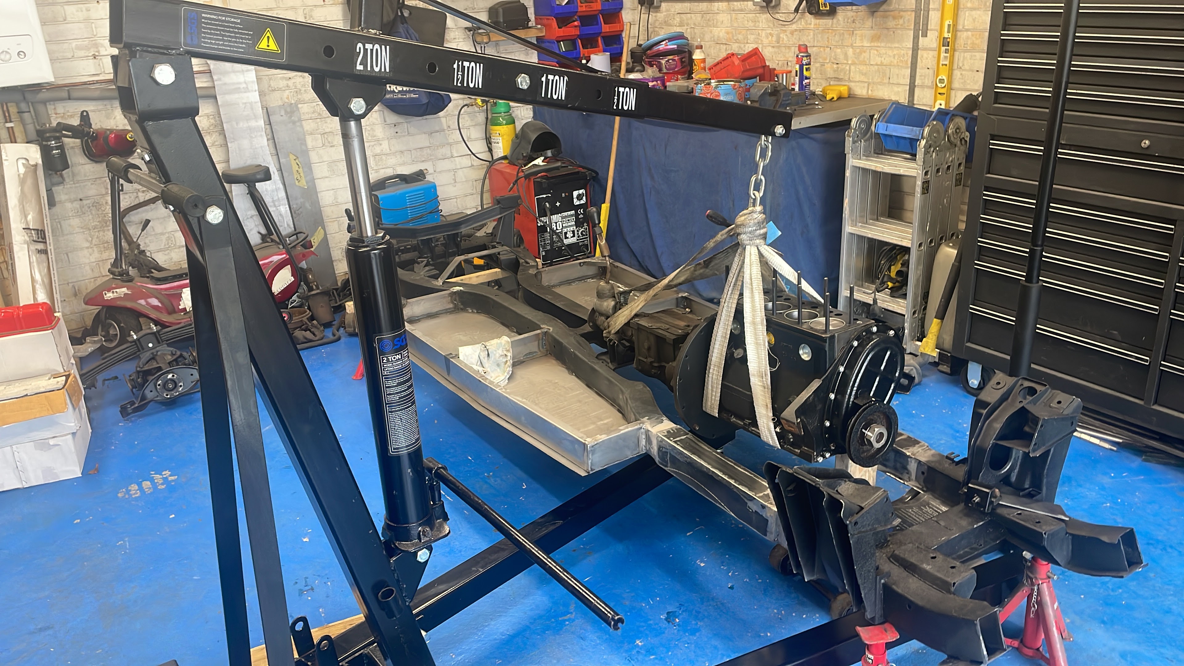
So another progressive day in the garage working on the chassis. I really am getting a tad sick of welding, grinding and constantly creating dust all over the place, luckily this is nearing an end now as it’s just the engine mounts left to sort and a few other little bits later on in the build. I have added to the growing garage tool collection and picked up a nice 2ton engine hoist from just down the road from my house for less than half retail price and it’s same brand as my trolly jack and engine stand so it all looks nice together. It has been on my want/need list for some time now, as last time I borrowed one from a mate and they are a tad difficult to move around without the correct transport, but essential for jobs like today. I really want to get the chassis built up now and rolling, but in order to achieve this I want to get the paint on it and thus needed to mock up the engine and gearbox into place in order to confirm the engine mount positioning. Then I wont have to keep painting in sections, and ripping off what had already been covered once.

I started off by mating the gearbox back onto the engine temporarily which also gave me a chance to remove the top gearbox cover plate and inspect the internals. It all looked in extremely good condition and the gearbox oil is clean and clear, so I’ll just be doing a cosmetic clean and fresh oil for this later on. Then I lifted the complete engine and box onto the chassis and lowered the rear gearbox mounts into place supporting the front of the engine with a block of wood on the trolly jack, this gives me a basic position for the engine mounts. The build guide states the mounts should be 312mm back from the suspension turrets however having learnt my lesson with the angles of the sills and floor pan sections it was better to mount the engine as it sits irrespective of what measurement were advised. The engine and box sit further back than in the Spitfire setup so hence the reason for new mounts needed, and when measuring them they are closer to 320mm back, however the guid does not stipulate from which point the measurements are taken so it’s a bit of a guessing game… However I’m happy with my mount position and when I had finished the engine was sitting nicely with no excessive stress on the rubber mounts.

I decided rather than tack welding the vertical mounts on the chassis top first and then adding the side plate afterward that I would weld the side mount to the upright on the work bench after I was happy with its position relative to the chassis top and side section. This was tricky as I wanted to have an element of adjustment back and forth within the original engine mount bracket on the engine, which has two elongated holes for the rubber mount to sit in. I wanted the rubber mount stud central within these holes either side so if needed the engine can be pushed back or forwards and not overly stress the rubber mounts when final fitting. The engine thought it’s life will want to rotate on the chassis during operation, and so one rubber mount will take compression and the other will get pulled/stretched as such. A rubber mount that does not sit straight on its mounts and is then subjected to these forces will wear out much quicker than one that sits straight, so an element of accuracy is important here with all these fixings. I managed to get both sides done relatively easily, and I soon had the engine mount brackets on the work bench so I could get a good strong weld on both sides of the side plate and front plate, before welding to the chassis.

My welding is certainly getting better and I now have 100% confidence in what is good and what is not, and with these mounts I need confidence that these will be strong and fulfilling for their purposes. Once both sides were constructed on the bench I needed to weld them to the chassis top and side. I stared by fitting them back on the engine again then tacking top and side plates when they were in the correct position. Then the engine and gearbox were lifted out the way altogether allowing me access to fully weld the mounts to the chassis and thus completing the job.
Once I had done this I then put the engine and box back onto the chassis but this time I could now move the engine crane and jack out the way and see how it all looked together as one….. bloody great in a nutshell. The engine sits nicely within the chassis with no clearance issues whatsoever and no uneven stress upon the rubber mounts either which is perfect. I did offer the cylinder head and valve cover back on just to get a feel for how it will look and then I lifted the body tub back on to make sure no issues with bonnet clearance on the top of the engine. All in all it was very satisfying, and more importantly means I can start to make provisions to getting an etch primer on and more texture bedliner protective paint.
The engine and gearbox have been removed again now and it’s back on the engine stand so I’m going to start scuffing up all the bare metal and preparing for primer and paint over the next few days.
So will leave it here for this update. I’m please that I have managed to get this done today, as I have a busy few weeks coming up. So I might find it hard to get some spare time to crack on. This will however allow the weather to improve and the ambient temperatures to increase slightly which will be advantageous on the next stage for primer and top coat… and then I can make a start on all the suspension and get this mother rolling!
So until the next one….


No comments:
Post a Comment