Saturday, July 15, 2023

Time To Stop

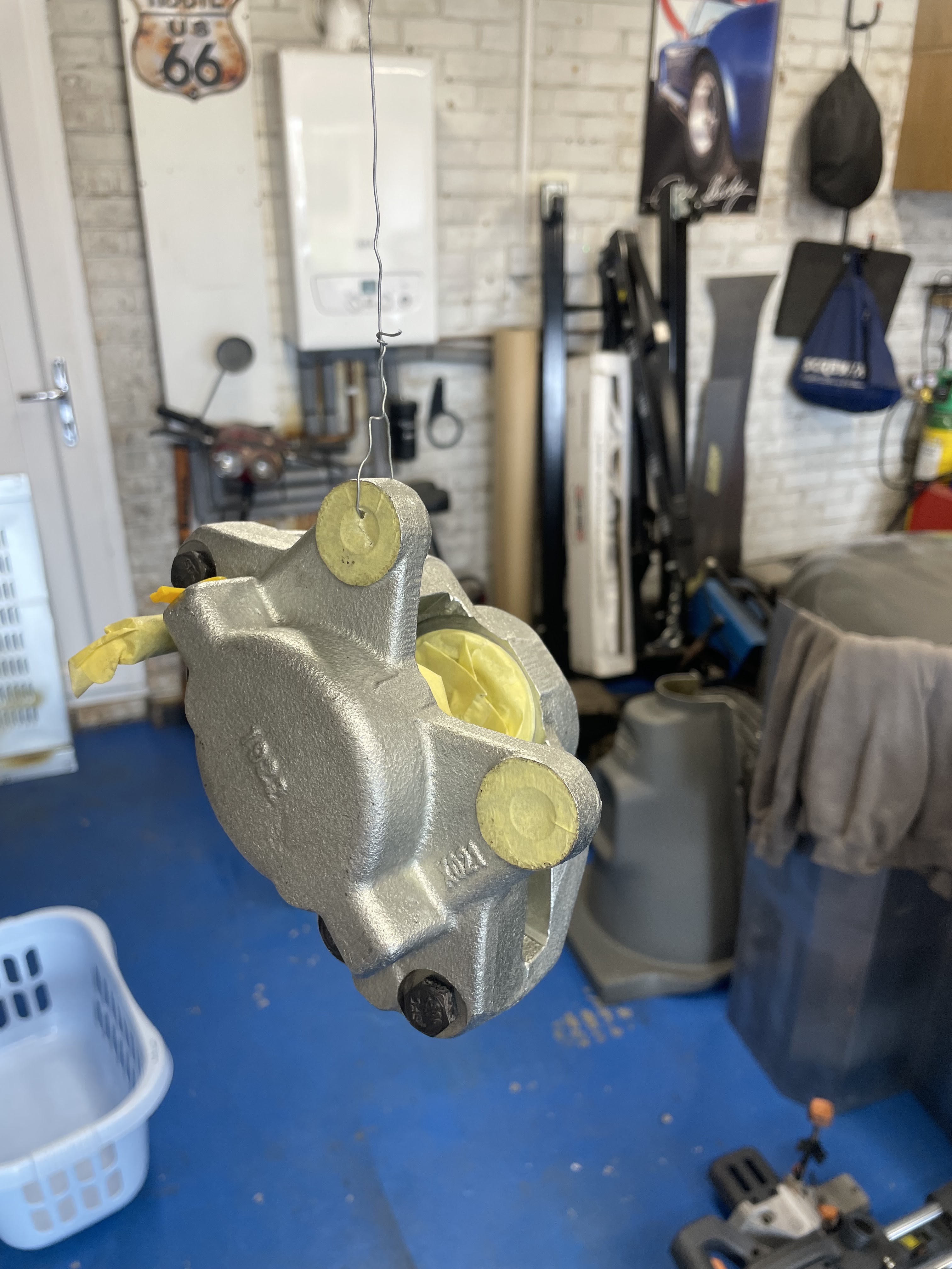
So now the chassis rolls it’s time to get it to stop rolling. I splurged a little cash on a front brake kit with some upgraded rotors as they are drilled and grooved to help with a little heat dissipation. First up really was to make the callipers cosmetically nicer, so the seals were popped out and masked up the areas that need to stay paint free. I gave them both a good degrease first as I want the paint to stay bonded to them as despite them being a nice galvanised finish it needs a good etch on top to bite into the surface and then for the paint. I took my time doing all this and did one calliper one day then the second calliper the day after then a top coat finish that will match the body of the car when finished, a luscious Ferrari Rosso Corsa red. I haven’t owned a red car for many years and whilst it’s a very bright colour it will look tremendous on this project when finished, and matching callipers is all in the grand plan with the attention to detail.


With the callipers painted and left to cure for a day it was time to start getting everything assembled and making sure it was going to fit ok. I started off fabricating some brackets that fix on to the top wishbone bolt that are the fixing point for the brake flexi to the ridged copper brake pipe. I spent flipping hours fabricating these little bits of bent steel cutting, filing, drilling and bending them both perfectly. Then I spent time etching them and painting them to match the chassis….. then to cut a long story short as soon as I had finished them and was really happy with how they had turned out, I went and found the original brackets in my box of bits that I have saved from the strip down…. Bugger. 
I then reverted back to the original’s after a good wire brush clean, etch prime and paint again. The originals are much more beefy the ones I made as I only had some 18gauge steel as opposed to these that are double bonded 3mm steel so really strong in comparison to mine….. belt and braces.


Not all is in vain with my now redundant brackets as they will come in useful for the bell housing bolts as they can act as a clip point where the brake line passes over the transmission to the servo so I’ve really just solved a problem way further down the line, way before I get to it. 

I moved onto the front hubs next and spent some time wire brushing and removing all the texture paint from the back of the hub to give a good machined face surface for the brake rotor to sit against. The rotors fitted perfect to the hubs and were torqued up to, in my opinion, a relatively low 88Nm and now with the rotors on the hubs the whole assembly went back onto the stub axles. I’m not setting all the bearings under load yet as they will be on and off many times again over the next few months during the build so just on finger tight for now.


 In went the brake pads that came in the kit, mixed reviews on these over the internet and the social media groups, still they will be fine for my needs and it’s not like brake pads are expensive or hard to replace later on if needed. The offside is significantly tighter than the near side on the pads, and keeping in mind no pressure or fluid is present yet it seems like the offside rotor is tad further offset on the calliper centre line. This could be down to the bearings not seating perfectly until they get some use or possibly just tight from being new. I’ll look into possibly adding a shim between the rotor and hub to bring it back or possibly one to watch after the first few miles on the clock after everything has settled in. These are fixed callipers and not sliding so the rotors should be fairly central in the calliper to avoid uneven pad wear over time.. a little niggle but “should” be easy enough to sort out.


I’m really pleased with how these are looking and will hopefully be pleased with how they perform also. They must be the smallest brakes I’ve ever seen in my life, but should be more than sufficient for my little Spyder. After all they will be doing less of a job then if a Spitfire body was going back on. 

Next up I think I need to tackle the steering rack. I have watched some really good videos on you tube on a full refurb which had easily given me the confidence to tackle it myself.  I will enjoy the strip down of that and cleaning it all up. I’ll need to order the standard perishable parts but other than that it should be straightforward to do and enjoyable… it’s nice to finally start building and putting stuff together again, very satisfying. 


Sunday, July 9, 2023

Rolling Once Again!

 So I’ve been having some issues with the fitment of the front hubs, specifically the bearings and stub axles. My last post showed how the outer bearing was a terrible fit on the stub axle. So bad I ended up returning the full bearing kits and replacing the new stub axles completely also. My replacement parts are much better fitting than the last ones, but I have still had to have a fair old fettle to get them to fit nicely and allow the bearing to fit correctly as they should. These replacements parts are sure as hell not built to the same tolerances as the original unit which makes things very frustrating to build up again. 

With switching the stubs and bearings I have gone from an impossible fitting outer bearing and good inner to a bad fit inner bearing, but the outer was good. In order to remedy the fit I have basically emery cloth the hell out of the stub after firstly using some various grades of wet and dry to reduce the overall diameter, this has been laborious to do but now the inner and outer bearings fit perfectly…. Phew! and more importantly they will now operate as intended with the specific end float and bearing adjustable as wear slowly happens. The bearing races were driven in using the bearing drift set I got many years ago, this ensures the race sits even and square in the hub, with zero damage to the face which can happen if using a punch to sit them in. Any damage to the race face will reduce the lifespan of the bearing significantly so these are a great tool to have in the garage. 

I also picked up some water deflectors for the front hubs, these are not available anymore as a replacement part so secondhand is the only option, I only had one when I got the car, but picked up a pair for £10 off eBay. I’ve wire brushed them back and then primed and painted them also. Some feedback on the forums is that they are not really required, however they were designed to be on the car so they are staying on mine…. They serve a purpose after all and my front wheels will be significantly more exposed to the weather then on the original Spitfire, so on they went with copious amounts of waterproof grease in the hubs and bearings. 
 With both sides done I was able to offer the hubs up and make sure I had no problems, I torqued up the stub axle nut (88Nm) and solved the previous issue where the steering arm wasn’t sitting correctly…. I had a washer between the hub upright and steering arm which was spacing it out unnecessarily. This was down to not remembering how I disassembled it all and trusting the schematics that you find online listing all the component parts with relevant part numbers….Shock eh, the internet having the wrong information everywhere. 

On went the old original wheels and were rolling again, great!!  Granted the wheels toe out whenever you push it, as no steering rack is on yet (need to start refurbishing this now) and also no front or back brakes either. I have all the brake components in my online basket, and the intention was to have all these fitted now at the same time for this update. However with all the tolerance issues I’ve been having I’m trying to broaden my supplier list and find someone who provides machined parts that actually fit correctly. So I’m holding back for the moment until I’m confident that the parts I order will be ok. 


So that’s it really for this update, short and sweet. I have lifted the body onto the now rolling chassis and must admit it’s looking bloody fantastic and very exciting. I will be ordering the final stage parts for the chassis in the next few weeks and so another little update should happen soon. I’m considering upgrading the front brakes discs and callipers to some vented units that are “supposedly” an improvement, however on a car that has no servo assist and will be significantly lighter than the original I really need to weigh up the pros and cons of making changes to the standard setup. 


Friday, June 2, 2023

It’s Building Time!!

As soon as the paint was dry and the chassis back in the garage it was time to start the build up of the suspension and axles. I started off fitting the differential and rear leaf spring which mount solid to the chassis and I’m using the original bushes here, they are really good condition and are virtually as new. The spring as you may know from previous blog instalments has been fully re-tempered/hardened and I have fitted some heavy duty poly bushings and leaf buttons to help with any sagg, this will not really become apparent until the full weight of the car is sitting on the ground and with my fat bum also in it. 

Next I moved to the front suspension and fitted all the new poly bushes to the upper and lower arms, I opted for the “comfort” version poly bush as opposed to “solid/hard” I want to really clock up some miles in this machine when finished and I don’t want to feel every bump through my spine really, and the comfort bush is still considerably harder than the original rubber units…
 
I then moved onto the front hubs and stub axles. My original stubs were far from acceptable when stripped down and were unable to be reused so replacement units had to be purchased. I had been reading up on replacement units being a poor fit and poor tolerance against the original units, but I presumed that buying replacement parts from reputable suppliers (Rimmer Bros in this case) that these issues would not effect me….. I was wrong. 

I pressed the new bearing races into the hub and all was going well during a dry fit prior to any grease and the first problem surfaced when trying to fit the outer taper bearing. The outer face of the sub axle has not been machined to the same diameter as the original which stops the outer bearing sliding onto the axle as it is too big in diameter. The bearing is essential to fit correctly here as you control the tension on the bearing using the castle hub nut and split pin…. Too tight and your wear the bearing out quickly, too loose and you risk damaging the stub itself and bearing failure and hub damage. This has really pissed me off to be fair as these were not really cheap replacements from Rimmers and they shouldn’t really be allowed to sell something that is not fit for purpose, however I will have a conversation with them after the bank holiday and see what resolution they are going to offer.

It is definitely the stub at fault here as opposed to the wrong bearing, as the replacement bearing fits perfectly on my old knacked axel stub, so that has stopped me going much further with the front end. I continued to fit the upper wishbones and front coil spring and shock, however until a perfect fit can be achieved for the front hubs I can’t continue with anything like the front brake assembly…. Bugger. 

If I continue to get crap parts in regards to these stubs I’ll have to consider a machine shop to turn the outer diameter down slightly in order to get the bearing to fit. Once done correctly they “should” outlive the rest of the car to be fair, so I’m keen to get things like this correct from the start… I’m sure as hell not going to start making compromises with components like this. 


So moving to the back end then… should be fairly straightforward….. should. First off was to put the new universal joints in. This is a straightforward job with aid of the bench vice, I have done these before with the Cobra build but was considerably more challenging when having to knock them in with a socket and hammer. So it was enjoyable to simply press them in with the vice and set the circlips in. Then I fitted the lower rear trunion bush, these are made up of sleeved poly bush with dust ring and covers. They are a bloody tight fit in the hub vertical upright and a considerable amount of swearing took place before they were fully fitted, however once fitted together it was easy to then fit the half shaft to the diff and ready to fit the shock absorber. 

The slight challenge to the rear end is the amount of tension everything is under to get all these bits back together without any serious load (no body, engine or gearbox weight) but with some logical thinking and use of a trolly jack and farm jack I managed to get everything aligned and fixed ready to make a start on the rear adjustable radius arms. 

I still need to overhaul the rear brakes but I whacked on the old wheels to see what suspension travel I had when sat on the floor and to gauge some overall width etc… fairly pleased with how this is starting to come together and definitely another step forward has been made.

Next on the list is to start on some mechanical components and to get the front and rear brakes trial fitted. I still need to order all these bits but these “should” be fairly straightforward and enjoyable to fit without too much head scratching. 
I do have to figure out what is wrong with the steering arm on the front hubs still, as despite putting it back together as instructed through the Haynes manual and various online diagrams I’m getting a issue when the offset face will not align. 

I’m simply either missing a spacer washer or it could be the brake heat/dust shield, that is the issue. I can’t recall exactly when I stripped it all apart, but until I can get the stub axel sorted for the bearings to seat properly then I have some time to figure out what is wrong. 

So everything is starting to come together fairly well, classic case when building cars of two steps forward, one step back. I’m going to have to start saving for some knock on hubs wheels and tyres or start searching for some second hand units through forums and eBay. I also will need to fire up the mig again to fix the rear radius arm plates…. Joy!! More grinding and making dust everywhere!,


Tuesday, May 23, 2023

More Paint than Bob Ross


Welcome back along, not a massive leap in progress here I’m afraid but the final paint finish for the chassis and this means I can start to build it all up now and get it rolling…. Phew, it’s getting heavy!

Over the past few weeks the weather has definitely turned and the second weekend of the month saw the thermometer showing a giddy 18 degrees, so out came the chassis from the garage and a good clean down, degrease and etch prime ready for more texture top coat. I learnt my lesson last time and have put down poly sheet all over the floor to protect the slabs slightly as the fall out last time got a tad messy and sticky. But this time it’s just a dusting of etch primer so shouldn’t be too bad, but prevention is better than cure and it was much easier to tidy up this time around. 

I started off by just scotch pad scuffing the chassis bare metal all over and a good degrease to remove anything that could potentially stop the primer from biting in to the metal and stopping the bond. I won’t be hitting with the black texture top coat until a week after to allow the primer to fully cure and less risk of any reaction. 

The first coat of primer went on well and has covered nicely, fair to say it uniformed everything and makes it look much better. So after an hour or so to tac off I flipped the chassis over and hit the underside of the floor pan also. 


Again it didn’t take me long to lash the underside with the primer also, and after another few hours I had got the chassis back in the garage waiting a week for the final finish. During this time I have also sealed all the panels with seam sealer.
The seam sealer does exactly what it says and will seal the panel join to protect it from corrosion and moisture. I have sealed all the internal and external seams along with the sills on either side. This “should” help reduce the risk of water ingress and corrosion setting in so it’s a preventative measure really, however it does neaten off all the seams and makes them look much better. The underside of the chassis now looks really good and the sealer between the chassis and floor pans just looks right as well as practical.

Next up is to get hitting it all with some topcoat. Same stuff as last time before I welded on the new floor pans and out riggers. It’s a 2k product called Gladiator bed liner (Raptor alternative) Its extremely hard wearing and gives the desired texture finish that I want. I deviate slightly from what everyone else does with this product and thinned it slightly to put a base coat down with a 1.7 gravity gun. Then after 20/30 minutes to tac a little I then hit it with the schutz gun to give the texture finish. I’m treating all the running gear to the same finish as the chassis, so when finished then the final product will hopefully look fairly uniform and consistent throughout. Once this was all done the chassis is ready to start taking some rebuilt running gear and a start on getting this project rolling.


I learnt my lesson off last time when I applied some paint and I have covered the floor with protective sheet, the fall out literally goes everywhere and is sticky as sh*t but all went well and the chassis was soon done. I erected my pop up gazebo again and used that to hang all the running gear components from with old rusty mig wire which allowed me to get a good coverage on all parts, and then it was just to leave it all to harden and cure…. Which didn’t take long with the weather being so good currently.


So fully painted chassis is back in the garage and is looking great, it will be a shame to cover it all up never to be seen again upon the rebuild. However the next update should be fairly soon as I had a delivery of nuts, bolts and bushes a few weeks back so I’m ready to start the next step straight away really. 


Saturday, April 1, 2023

Breakout The Crane!!


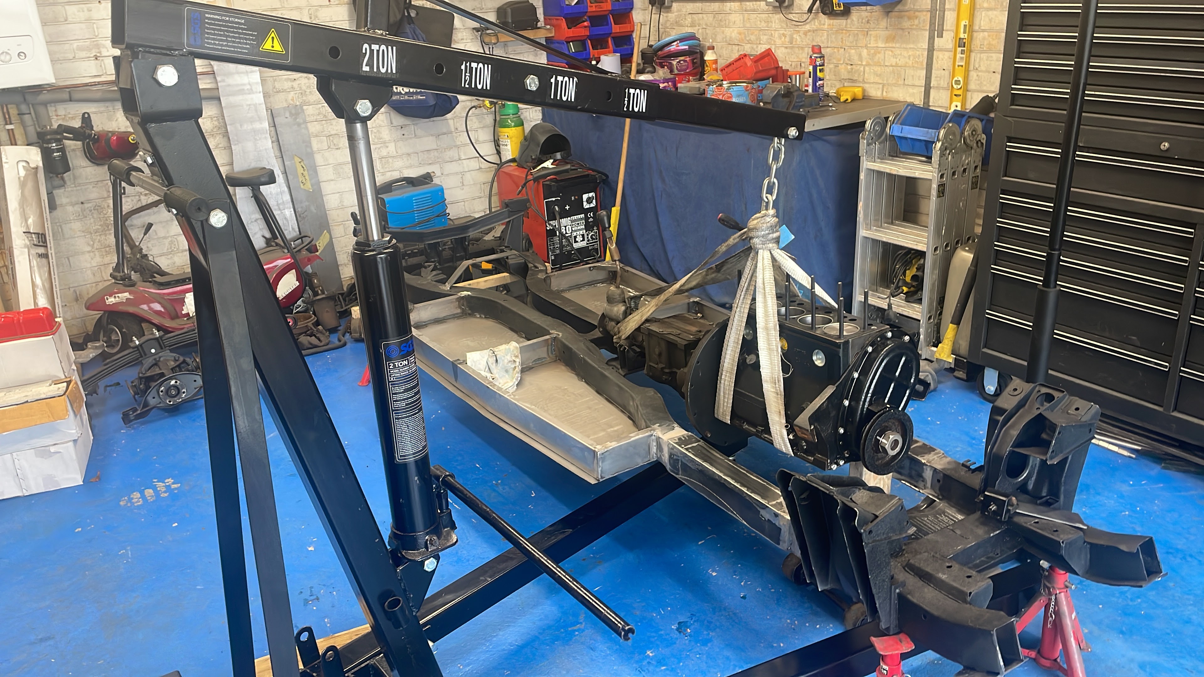
So another progressive day in the garage working on the chassis. I really am getting a tad sick of welding, grinding and constantly creating dust all over the place, luckily this is nearing an end now as it’s just the engine mounts left to sort and a few other little bits later on in the build. I have added to the growing garage tool collection and picked up a nice 2ton engine hoist from just down the road from my house for less than half retail price and it’s same brand as my trolly jack and engine stand so it all looks nice together. It has been on my want/need list for some time now, as last time I borrowed one from a mate and they are a tad difficult to move around without the correct transport, but essential for jobs like today. I really want to get the chassis built up now and rolling, but in order to achieve this I want to get the paint on it and thus needed to mock up the engine and gearbox into place in order to confirm the engine mount positioning. Then I wont have to keep painting in sections, and ripping off what had already been covered once.  


I started off by mating the gearbox back onto the engine temporarily which also gave me a chance to remove the top gearbox cover plate and inspect the internals. It all looked in extremely good condition and the gearbox oil is clean and clear, so I’ll just be doing a cosmetic clean and fresh oil for this later on. Then I lifted the complete engine and box onto the chassis and lowered the rear gearbox mounts into place supporting the front of the engine with a block of wood on the trolly jack, this gives me a basic position for the engine mounts. The build guide states the mounts should be 312mm back from the suspension turrets however having learnt my lesson with the angles of the sills and floor pan sections it was better to mount the engine as it sits irrespective of what measurement were advised. The engine and box sit further back than in the Spitfire setup so hence the reason for new mounts needed, and when measuring them they are closer to 320mm back, however the guid does not stipulate from which point the measurements are taken so it’s a bit of a guessing game… However I’m happy with my mount position and when I had finished the engine was sitting nicely with no excessive stress on the rubber mounts. 

I decided rather than tack welding the vertical mounts on the chassis top first and then adding the side plate afterward that I would weld the side mount to the upright on the work bench after I was happy with its position relative to the chassis top and side section. This was tricky as I wanted to have an element of adjustment back and forth within the original engine mount bracket on the engine, which has two elongated holes for the rubber mount to sit in. I wanted the rubber mount stud central within these holes either side so if needed the engine can be pushed back or forwards and not overly stress the rubber mounts when final fitting. The engine thought it’s life will want to rotate on the chassis during operation, and so one rubber mount will take compression and the other will get pulled/stretched as such. A rubber mount that does not sit straight on its mounts and is then subjected to these forces will wear out much quicker than one that sits straight, so an element of accuracy is important here with all these fixings. I managed to get both sides done relatively easily, and I soon had the engine mount brackets on the work bench so I could get a good strong weld on both sides of the side plate and front plate, before welding to the chassis.

My welding is certainly getting better and I now have 100% confidence in what is good and what is not, and with these mounts I need confidence that these will be strong and fulfilling for their purposes. Once both sides were constructed on the bench I needed to weld them to the chassis top and side. I stared by fitting them back on the engine again then tacking top and side plates when they were in the correct position. Then the engine and gearbox were lifted out the way altogether allowing me access to fully weld the mounts to the chassis and thus completing the job. 

Once I had done this I then put the engine and box back onto the chassis but this time I could now move the engine crane and jack out the way and see how it all looked together as one….. bloody great in a nutshell. The engine sits nicely within the chassis with no clearance issues whatsoever and no uneven stress upon the rubber mounts either which is perfect. I did offer the cylinder head and valve cover back on just to get a feel for how it will look and then I lifted the body tub back on to make sure no issues with bonnet clearance on the top of the engine. All in all it was very satisfying, and more importantly means I can start to make provisions to getting an etch primer on and more texture bedliner protective paint.


The engine and gearbox have been removed again now and it’s back on the engine stand so I’m going to start scuffing up all the bare metal and preparing for primer and paint over the next few days. 
So will leave it here for this update. I’m please that I have managed to get this done today, as I have a busy few weeks coming up. So I might find it hard to get some spare time to crack on. This will however allow the weather to improve and the ambient temperatures to increase slightly which will be advantageous on the next stage for primer and top coat… and then I can make a start on all the suspension and get this mother rolling!

So until the next one…. 


Sunday, March 12, 2023

A Floor In My Plan!


Well it would seem that I should use more logic and less stupidity when working on this project. I offered up the floor pan sheet which is laser cut to the correct dimensions, and despite me measuring the new outriggers correctly you can see pictured here that it’s well out. I need an even 20mm sill lip in order to mount the body on. The build manual does state to check the width and narrow the outriggers if needed. So I just needed to reduce the width of the centre support and adjust the angle of the front side profile slightly. Bit of a ball ache really but all part of the learning curve I suppose. Still it should make constructing the other side much easier and straightforward.

So another few hours messing on and it was sorted, a nice 20mm even sill flange front to back. Now to start on the other side. The floor pan on these pictures is just measured and set in the correct place then clamped onto the chassis and outriggers allowing the sills and other dimensions to be checked first. Once the other side frame is complete the floor pan is then welded to the chassis which will also add to its increasing strength. If you are going to attempt a build yourself of this car then measuring and clamping the floor pan should be the first thing you do and will make fitting your front, centre and back outrigger considerably easier to construct, whilst keeping within the tolerance for the dimensions.

The image above shows where I have finished the main frame now and removed the floor pan sheet ready for trimming. It has been fully marked up and the centre of the floor is cut/removed as so the prop shaft will be accessible from underneath the car. 
I have welded the floor pan to the chassis now and allowed sufficient overlap underneath to allow a seam weld along the inside face of the chassis rails. It is stitched on around the perimeter on the inside face and the outer joins will be sealed with some seam sealer to eliminate any water ingress. 

I intend to hit the whole chassis again with the bed liner texture paint, as it has taken some abuse during the construction stages where I have had to strip it back to allow the welding to penetrate. I will treat and prep the bare surfaces first to a good 2k primer then top it with the same texture black bed liner. I can’t really do this until the ambient temperature increases slightly as today was barbaric in the garage and I’d be surprised if the temp was anything above 2/3 degrees…. Still the enthusiasm of progress kept me warm….. sort of! 
Now the chassis has some considerable weight to it, and manhandling and flipping it over was getting bloody tricky on your own. It wasn’t particularly easy before however now with the added weight of the diff, main spring, new floor and outriggers it’s nye on impossible to lift and shift where you need it to be in order for access for welding. Still it’s nearly time to build up the running gear and get the whole thing rolling, that will be a good milestone. 

I’m happy with how this is turning out and my confidence in welding is massively improved, but I’m slightly sick of the constant weld, grind, weld, grind, tidy up process already. The satisfaction of constructing something substantial out of metal is immense, however the construction process is a tad laborious really… all for the greater good mind.

Next up is the front body mounts, which double up as the radiator fixings also. These are simply twin flange bit of steel that cap the front chassis rails, where we removed the original bonnet hinge brackets. 

I offered the body tub up onto the chassis just to basically check that all the floor sections were acceptable and no further adjustments was needed. Then after a play around with the front body supports/radiator brackets I decided to leave them until later on. If you see pictured here that the front support will need some angle adjustment in order for the top 10mm flange to sit on the chassis rail, and this is not really possible to determine yet, until I’m closer to fitting the body tub permanently as a cannot determine it’s final position yet. When each of these brackets are fitted they then have a further second flange bracket welded onto them at 90degrees which in turn then creates the mounting point for the radiator. 
  I have retained the radiator from the donor car and so now it’s time to start getting it overhauled and ready to be used again, I have considered an alloy replacement, however the majority on the market are superseded units for the Spitfire and are considerably wider than original and will not really be suitable for this project… that and the cost of the bloody things are barbaric in comparison to an original reconditioned unit. 
The second picture here shows the radiator support bracket that will be welded to the body bracket, it will give me ample room for fitting the radiator and allow some further fixing points for a cooling fan (either push or pull) I’m intending to totally over engineer the cooling system for this project. My Cobra is great when moving but sat idle for any medium to long period and the overheat becomes a serious concern, and the cooling fan is grafting at full capacity… so not really very practical. Now I know this won’t have a whacking great V8 in it, but I want it to be robust enough to sit on idle all day long with no airflow through the nose cone and still hold temperature correctly. This will simply be a basic thermostatic controller within the top hose kicking the fan in and out as needed, and secondly the fan fitted must pull/push the capacity of air requiring to sufficiently cool the radiator. The original viscous fan I think will be pretty much redundant on this setup. I have been researching about changing the viscous unit to a standard direct drive fan off the water pump, however with the movement of the radiator and engine within this car I can’t see at this point how it will be anywhere near useful if fitted and so I plan to just do away with it all together. Lots more to do before I start considering these decisions mind… like where I’m going to put my size 12 feet!!!

With the body offered onto the chassis it was difficult not to get a tad excited and start planning future bits here and there. One thing I did notice was how narrow the foot well is. Again comparing with my Cobra I have sod all room in that to rest my left foot when not operating the clutch, and whilst this image here is slightly accentuated because of my rigger boots, I’m still going to have similar issues on this one, unless I start planning some changes now. On reading the manual it’s advised to cut the top flange on the offside outer section and fold down to give more room for your right foot on the accelerator, however I’m going to start considering making a wider footwell as there is a good 3-4inch between the outer sill section and the curvature of the body tub. Again reading the build guide it’s advised to utilise this space for brake/fuel lines etc… and I’m also considering locating the battery in the boot so the main battery cable can run down here also, however none of these components demand as much space as there is and the operation of the pedal box is far more important than cable runs. Also their is the nearside void that could be utilised for all this as the passenger footwell can be narrow as they will not be operating anything with their feet. 
Again with the body tub offers onto the chassis it was mandatory to sit in and make “brum brum” noises with my youngest sat shotgun, thinking I’m a total wally. Still it was a tad exciting to imagine what the finished product is going to look/feel like and start to get a feel of how it’s all going to be. 

If anything I’m a tad daunted with just how much work and construction is actually required building this, and as I’ve said before it is not just a bolt together kit, so I hope my brain and body hold out long enough to complete it…. And my bank balance!
Now I really need to start getting all my running gear sorted so I can start the rolling chassis, this is going to be a relatively tidy sum of parts along with adjustable suspension etc… but again, all very exciting and enjoyable. 

Sunday, March 5, 2023

Chassis time, let’s get the party started!!


Well I think now it’s time to step this project up a gear, I have had some uncertainty’s and doubts over the winter period but with all that behind me and the main fabrication parts now available it’s time to crack on. The chassis parts are now all with me from David at Morfabrication and are ready to start getting measured and cut for fitting. We had some teething problems getting the parts all correct, however we soon got it sorted and now have a chassis kit produced and a cost price sent to Mick at Fiorano. So future kits might be supplied through Fiorano possibly from a north east supplier, we shall see what the future brings. 

With all my chassis bits now in my garage it was time to really get my head round the build and start making some progress. This build is totally different to my AK Cobra that I built a few years back, there is significantly more fabrication and building as such as opposed to just a bolt together project. 

I started by temporarily refitting the diff, as this machined face provided the datum point to which all floor pan measurements are taken. The floor pan is made up of a front, centre and rear outrigger with a side profile angled the same as the sheet floor. Because the outriggers are

just welded onto the chassis sides it leaves the original chassis as standard hence just a technical re-body for registration process. There is also the rear handbrake bridge which creates the fulcrum point for the handbrake cable, which is something I’m determined to make functional as opposed to a novelty like on the Cobra. Every year at MOT the handbrake efficiency on the Cobra is a bone of contention, it’s notoriously weak on the gen1 AK kit with inboard rear callipers…. But not on this project!


I spent considerably longer than was needed probably checking all dimensions and creating a drawing with every possible measurement sketched on it including angles of the side profile cut which involved some GCSE maths that I haven’t used in nearly 25 years, but still after checking all measurements again and again it was time to fire up the mig and start welding some bits together. 

With each outrigger I have spent some time profiling the end cut to the chassis, which should create a good strong structure when all fused together with the art of welding. This was tedious really but important as it keeps the accuracy for the overall dimension of the floorpan which will support the body, along with the firewall bulkhead. The sill is created by the floorpan overlapping the outrigger when welded together (I’ll cover this later in the blog when I get to it) 
  I initially tacked the outriggers on to allow for any adjustment within the geometry of the build up. This allowed me the chance to create one completed outrigger section and to check all my dimension according to the drawings and datum point for accuracy before finally stitch welding it all together and making a solid structure. 


I always envisaged the chassis being considerably wider than this when browsing pictures online. But after checking again all my measurements and cuts I’m more than confident that it’s all correct. Again I was surprised at how strong the structure now is even without the central outrigger in place like pictured here. The bulk of the strength will come from the steel floorpan that will get stitched to the underside of all this substructure and welded round the perimeter and centre outrigger. I have only had time to get the one side done so far, but it’s just repetition for the other side and then to flip the chassis over to start on the floor sheet, made from 16gauge steel.

I really hope that more people will find this blog in the future and use it as a guide to start their own build. So little information is available online for these vehicles and again so few of these vehicles are ever seen at shows etc… so fingers crossed this blog will help buck the trend and get more people building as opposed to just saving up money to buy one built already. It’s a steady decline bred into children from primary school that to be “practical” or “hands on” is just not desirable in the modern world we live in. However the industrial revolution is something we should embrace and be proud of…. Not apologising because it might have upset someone’s feelings or it doesn’t conform to you current standards of life or ethics. 

Last up was to weld up the handbrake bridge onto the chassis. Caution is advised in the manual as if you use the original donor cable, then it may have stretched slightly and not allow as much adjustment as required to get an effective handbrake. I intend to fit a brand new cable, custom made if needed, to give a more than adequate handbrake. And I’m considering an external hand break lever similar to that on some more vintage vehicles. Another option is a cosmetically nicer chrome hand break leaver from a MG midget. These are much nicer to look at than the grubby plastic Spitfire unit that I still have…. However these decisions can be made later on. 

Next update in a week or so probably, just showing the other side complete and the floor pan in hopefully. I’m going to have to start a shopping list to start all my running gear and bushes so I can get the chassis rolling!…. Now that’s exciting…. For me anyway!