Saturday, June 29, 2024

Time To Tape The Bonnet


I’m still halfway through writing another blog update covering the steering column install, however I need around £200 to order some parts and I just don’t really have the spare funds yet, so will have to wait a few weeks until I can finish that update. However this is a great little progression step that I have had planned from the early stages of the build. I don’t want rubber or neoprene seals round the bonnet and engine bay as I wanted a more vintage look to the car. So I have opted for a thin seal of bonnet tape to stop the bonnet rubbing against the body. This acts as a cushion between the bonnet and the flange on the body and will look extremely period when fitted. 

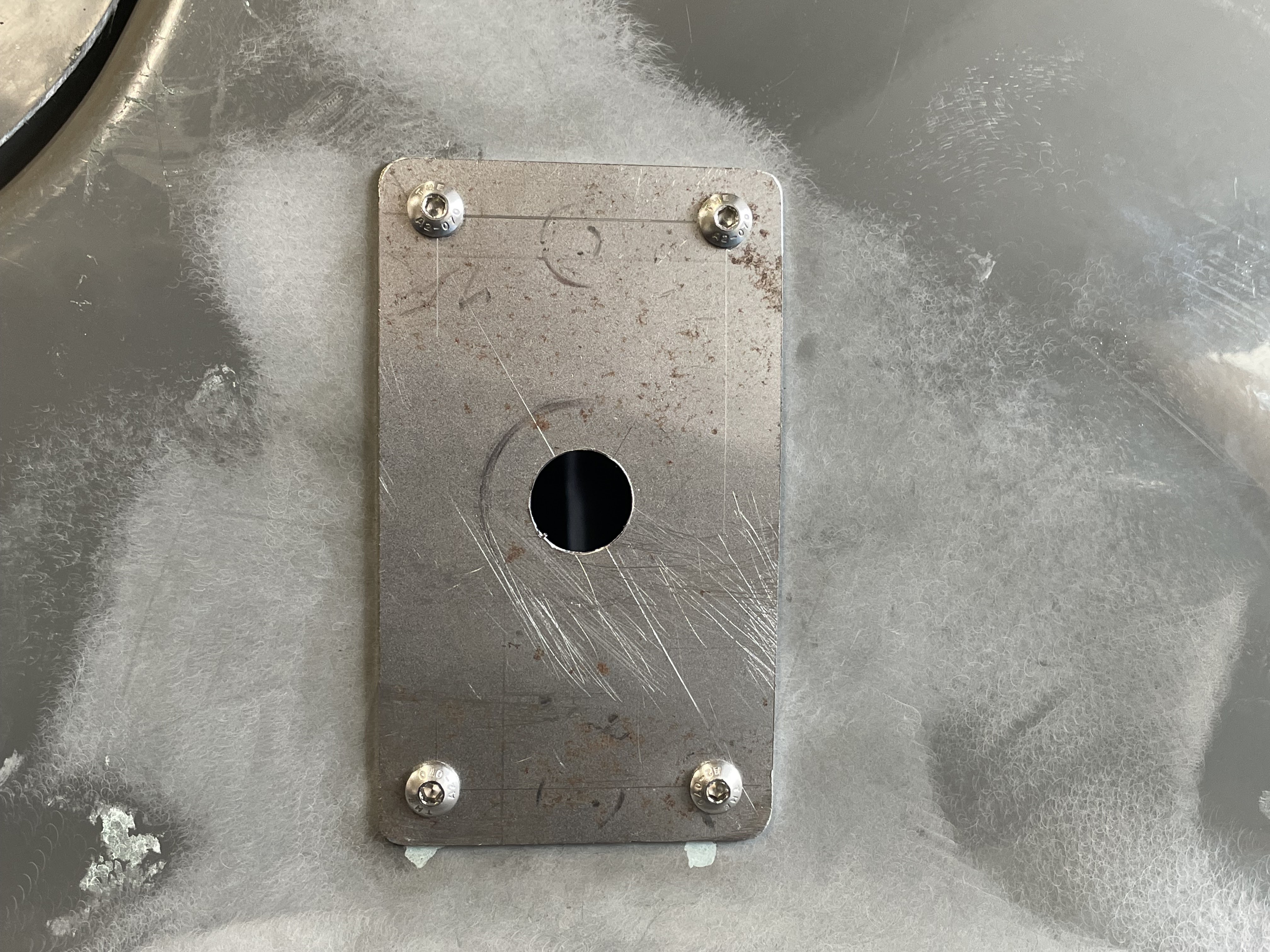
In order to fit the tape I don’t want to use adhesive or clips really, as in my opinion with adhesive it’s just a matter of time before it fails and makes a mess of the paint and bodywork and whilst clips would work they would also potentially scratch any sections that are in contact with them. So I have opted for my own style of installation, weaving the tape between small slots cut into the body, zero risk of any scratches and impossible to work its way loose when installed.

I started off making a template of the correct size slot/hole I needed for the tape with some thin cardboard. Then with some masking tape on the mounting flange I started to measure and mark where I wanted my cuts to be. I have spent some time on this planning the route of the tape, and measuring so that each section is consistent in its spacing and more importantly symmetrical from offside to nearside. This was relatively easy and just took some time planning the tighter curves in the panel on the lower edge and was easy to just continue my way round the full perimeter of the body tub. 
Once all the marks were made I used my dremel multi tool and a small drill bit to make the openings required for the tape to pass through, by drilling two holes at either side of my marks then elongating the holes to make a small oval cut in the body. 


With the tape woven in and out of each slot it was looking really cool and I was extremely pleased with such a trivial issue that now looks superb, and will look even better once the body is painted…. Another tick in the box of “attention to detail” 

I still need to find some bonnet hinges (same as the boot) so I can fit the bonnet but I’m keeping my eyes peeled on eBay for another bargain as they are around £80 from S&J new which I don’t really want to spend when the same boot hinges cost only £15 on eBay….. patience I suppose. 
 The bonnet tape came from Woolies and only cost £15 so not expensive whatsoever for the overall finished effect. I used a total of 4 meters which has given ample excess to cut and secure at the start and end point at the front centre of the engine bay. I will be securing these ends with a small rubber bonnet spacer and fixings once I get my hinges and can actually start fitting and spacing the bonnet.

Last on this update I want to show you why you must measure and check everything for symmetry when working with kit cars and specifically fibreglass kit cars. You can see on the image here the flash line in the moulding of the body, which could easily be presumed as the centre line for the body tub….. it is not!
When I measured a centre line from between the end of each side of the bonnet tape you can see the mark on the masking tape is easily a good 2cm away from the flash line, so if using that flash line as a centre point it would knock everything cock skew off centre and really fudge things up! Granted there is a small tolerance within this because of the nature of fibreglass and its shrinking whilst curing (which takes a year or so technically to fully cure) but it’s much easier to be conscious of these potential pitfalls during the build and act accordingly. In this case I can confirm the centre line by placing the bonnet in situ and the masking tape line should be central to the bonnet scoop opening give or take a millimetre or so….. and it is, boom!! In fact it only accentuates further, how far off the flash line actually is!


Saturday, June 15, 2024

Bending Again… Attempt Two!


I’m trying to push this project on a little with limited funds currently due to life, but hey ho I’m always looking for a bargain or a nice cost saving alternative without compromising quality. So to totally contradict that statement slightly I’m spending some more money on some steel tube to redo the front support frame. The first one I did I was a tad overzealous with the gauge of the steel tube and it just wasn’t working well. 

I picked up a 3 meter length of 2.5mm 1 inch tube and I spent some time mimicking the bends of the previous attempt. This time I started with the near side section, slowly bending each bit using the tube bender. This was working nicely and the smaller diameter tube was working just as well as the previous attempt. However this time I wanted the offside section to follow the contour of the body tub so that involved starting to bend one half up first to follow the radius of the cockpit body.


This was a little time consuming but after lots ant lots of little adjustments here and there it was pretty good really and fitted well. You can see here how it now follows the full shape of the body and will give me more space when the dash is fitted to fit the gauges, without them voiding on the frame. Next I moved on to some lower fixing brackets that will be bolted onto the outer chassis rails, these were made from offcuts of 2mm steel and welded onto each lower leg of the new brace support. I’m also going to fit a tube section from the top middle to the front bulkhead which will add even further strength to the whole setup. 


The centre support section was simply made using an off cut of the tube cut to length and welded into place on the frame and a plate section the other end which is aligned and drilled for the bulkhead fixings. All of this might seem fairly trivial and straightforward, but it takes a huge amount of time fitting, removing, trimming, measuring, welding etc… etc… however when all sorted and finished it will all be hidden from sight behind the dashboard with only me really knowing how much work was involved getting it right. 


I am however this time around 100 times happier then my last attempt, and this will be more than sufficient to support the steering column, when I weld in the horizontal brace also. This will have to wait until some further mock ups of the steering column and extension shafts have been done as these will dictate the height and position of the brace bar. I’m going to remove all this again soon to prepaid it to be painted, as I want everything uniform and looking professional. 


Another bonus is that I can now play around with my dashboard setup and positioning of the gauges before I commit and get a sheet of steel to actually make the dash itself. It will be good to get the steering column in now and I think this is going to be a tad tricky in regards to the rack position and getting the steering column sections aligned nicely without creating tight spots from lock to lock…. But this is all next on my to do list!

Friday, June 14, 2024

The Cheapest Flange I Have Ever Had!


Well it’s been a while since I last did an update, but you can rest assured I have been scratching about and keeping my eyes peeled for bargains and auction specials. So we’ll start this update with my fuel system. I managed to find a Brasscraft fuel filler flange with locking insert for the grand total of £25. Granted I still need the Aston style cap (like on my Cobra) but this flange piece alone is easily over £100 and ticks all the box’s for me. I specifically wanted a locking insert on my fuel filler as this acts as a seal to the fuel tank, along with the main cap. I also wanted the flange to bolt to the panel as opposed to just a classic mini style fuel cap that just grub screws onto a filler neck with no support other than the 50mm fuel hose onto the tank itself. Granted this fuel flange does have a little trauma damage to one of the thread holes but I’m hoping to be able to file/polish it back enough to totally disguise it…. Fingers crossed. 


So to fit the fuel flange I first of need to prepare the mounting position on the body. The body tub has a raised area which is considerably smaller in diameter than my chosen filler cap, but luckily I am just going to use this as my cutting diameter as my flange is big enough to overlap and give me a secure fixing point and enough movement to align with the fuel tank below. So out with the multi-tool and a simple cut out and neaten off the edges. Then I dropped in the filler flange and got everything central and measured up correctly so I could mark the bolt fixing positions keeping them symmetrical. 


The fuel flange dropped in perfectly and I was able to mark and drill the fixing bolt positions. I need to get about 6” of 50mm fuel filler hose to fix the filler flange to the fuel tank still and more importantly now I need to start to hunt for a 3 1/2” filler cap that will thread onto this. I will if i have to buy a new one but I know about 10/15 years back when the Cobra was getting built, how much i paid then, so with inflation etc… etc… it could be a tad eye watering for a new cap from Brasscraft. Still I’m in no hurry as such so I can keep my eyes peeled and hunt every auto jumble I go too and see if I drop on. 

I bolted the filler flange into place and I have used the same machine screw stainless fixings as on the bulkhead and peddle box  as so to keep the theme of the build consistent and the attention to the detail. 

I also just borrowed the Aston cap from the Cobra for a second so I could visualise how it would look and it looks bloody terrific in my opinion. On the Cobra, with the filler neck being recessed it hides the cap slightly and whilst it’s clearly visible here it is top and centre and a real feature point for the car, so I’m pleased with that. However in true kit car building process, you venture away from the build manual and you create further problems… but only little in this case. You can see here that the filler cap latch sits fairly far back and so when the boot opens now I am going to have to restrict its fully open position and so the boot lid won’t void with the filler cap. The boot opens more than sufficient for normally use but it now can’t move past the vertical position and stay open on its own, still easily solved later on down the line with a boot hold latch which are easily obtained, or I might consider a nice bit of chain or rope whichever looks best. 


Saturday, April 13, 2024

Lights and Spokes and Hinge

I managed to pick up some boot hinges off eBay for only £15 and with these being S&J hinges (same as on my Cobra) they are awesome quality and normally retail at around £85 so that’s a great saving. Fitting these is fairly straightforward and a nice little job to crack on with. I started off setting the boot lid as square on the body as possible then marking lines agains the body on the front, back and both sides. Then I measured off the centre line to the outside edge of each hinge as so they were spaced equally. I played around with the spacing for a bit before settling on eight inches off the centre, as that to me is what looked best. I masked the body and boot with tape and scribed the outline of each hinge which allowed me to mark the drill point for each stud. 
I had to use some blue tac to create a spacer between the body lip and underside of the boot in order to sit the boot lid level with the body. I will be fitting a rubber seal trim when all finished to also help with keeping the water out. I have ordered a keyed cam lock to secure the boot and I’m wanting some tan leather boot straps on the back edge also. But none of these have been delivered yet and are not that critical to fitting first, still it will be good to get all the fixing positions marked and drilled prior to prepping all the panel gaps. Once the boot and body were drilled the hinges simply fit on and are secured underside with some penny washers and nuts. I have used some dome nuts on the boot lid as they look nicer when the boot is open, and attention to details is what it’s all about!
Once the boot hinges were sorted I moved onto the wheels. I have had the tyres from the old steel wheels fitted to my recently acquired wire wheels.
I didn’t want to spend money on new tyres yet simply because tyres are date coded nowadays so if this project takes me another two years to finish then I won’t have lost any tyre life during this time. These tyres are in no way safe to use on the road but more importantly they are the correct size so they will allow me to fabricate my metalwork and fit the arches. I need to put a good bit of planning into these arches as I don’t want them to crack or come off when driving any bumpy roads. I specifically want the arches to be spaced off the tyres and to travel with the suspension movement. So this will require fitting to the rear of each hub as opposed to the body itself. 
It’s awesome to be able to see how the car will look with the wheels on now, it really makes the car look longer in my opinion, and the twinkle of the red calliper through the front spokes looks tremendous.

So with the wheels also now fitted and the chassis rolling on the wires I was able to continue with the next job, the headlights. I have previously fitted the outer and inner mounting brackets and all I had to do was open up the centre hole to accept the headlight bowl spigot. 

I splurged a little with the headlight bowls and went with the stainless steel units as opposed to the chrome on brass. Yes they were three times the price but they do look fantastic and really feel like good quality bits to bolt on. I had previously picked up some 7” headlights on a deal, the same as my Cobra (Lucas style P700) as I really like the look of these lights and I think they look perfect period for what I’m trying to achieve. They simply fit with the large hollow thread shaft and retaining nut from the inside. 


I opened up the centre hole with a step drill slowly until I was able to pass the spigot through and fix easily from inside with the lock washer and nut. Once I had fitted both headlights I was not happy with the overall level of each headlight. The off side sat 50cm from the bottom of the headlight bowl to the floor level and the near side sat at 51cm. I couldn’t drill one of the outer backplates again as it then would not be central and would look odd. I decided to remove the offside rear bracket and fill all the holes in the body before refitting the whole thing again and re making the offside rear bracket again from scratch in order to get the headlights to sit even. You can see in this picture the original holes just showing under the outer bracket. The mistake I made was I simply made both rear bracket’s initially to the same dimensions, just bent opposite for each side. This then dictated the mounting position for the front bracket which in hindsight was way off. Now I have remade the rear bracket which is longer than the near side it allows each outer bracket to sit evenly. Now if I measure from the bottom of the outer plates to the lower body edge they are both sitting at 9cm and thus the centre holes are both level for the headlights. 
I refitted the offside headlight and was relieved when I measured to the floor level and both lights are at 51cm and sitting level. This photo shows how they both look, as before I would have been ashamed to picture my bozz eyed attempt at the fitting… it just looked odd. Still all sorted now so I’m able to get on with the next job on the list. 


Friday, April 5, 2024

Tanks A Lot


I have managed to pressure up the brakes now and I’m pleased to say all seems well. I’m getting a good feel from the pedal, but I’m hoping for a slight improvement once the pads and shoes are bedded in a little, that will come in time obviously but I have bled the system fully and all brakes are engaging properly. The secondary line was a tad tricky to fit simply because of my cut out box that I had made in the bulkhead for the master cylinder. It only gave me enough space to fit a banjo union  (see picture) as I didn’t have the clearance to get a 90 degree bend on the pipe. The banjo seems to have worked well and I have ran the pipe down to a bulkhead fitting by the outer sill. This will run the feed back along the sill to the rear brakes. I have purposely left this brake pipe loose until I have my front dash and steering hoop bar fitted. This is/will be fitted down next to the outer sill so I need to rout the brake pipe around all this once it’s done. 


Next job was to tackle the petrol tank install. I have already fitted to two main sections of the boot floor and concluded that the boot floor alone will not support a fuel tank when it’s full and under road vibrations and knocks. My plan was to make a small but sturdy bracket that will fix to the rear bulkhead internal to the boot and then the recess in the tank will allow the full weight to be distributed on that, rather than the boot floor. I made some measurements then set about with some cuts of 6mm angle bar and fairly quickly had welded up a lovely solid bracket. 


I spent time cutting the angles correctly and making sure my welds were solid then I added some carpet to the top face as so it wasn’t metal on metal fitting, which would be silly. I also used an old bit of rubber hose split and fitted to the bottom of the tank seam to again help reduce the risk of metal on metal fitting. The back section of boot will also be carpeted to help reduce this risk and help dull any road noise. The bracket seemed to work really well and would certainly take the weight it will be subjected to. I will have to also make some brackets for either end to stop the tank from sliding left to right and hold it securely also. Can’t risk a tank full of fuel breaking free when hitting a road bump or hard corner. 


The bracket was easy enough to fit as once I had drilled two bolt holes through it I could just offer it up to the rear bulkhead a scribe through for the drill positions again. This was quickly done and the bracket is going to do a grand job of helping to spread the load of the tank. It really has worked well and should function perfectly. I now need to start making some brackets for either end of the tank to further support and stop any lateral movement when going round corners. I made these from some bits of angled steel that I measured and cut accordingly. I started off making the back brace by crudely measuring the centre points from two of the mounting holes on the fuel tank. I then just increases this by about 5cm overall to give me the length for each back piece. 
Then I measured from the tank flange seam to the rear edge of the tank which was roughly 12cm, then added a further 1cm onto this length as I don’t want the tank to physically rub against the rear bulkhead. I made four lengths and welded them to each back plate and finally finished the front face of the bracket with a small plate section in order to bolt the tank through. 
After a few trial fits I managed to scribe each bracket where they needed drilling for the fixings. The rear of the brackets will be simply bolt clamped onto the rear bulkhead and I have welded a nut on the backside of each front plate, so the tank can simply be bolted onto the brackets. 
I had some carpet already that I have lined the rear bulkhead with and the lower front boot floor, and with the tank back in it was rock solid. I’m extremely happy with how this has all gone and next I will be fitting the rear seat belt supports next which will be a couple of tube sections that run from the bulkhead down to the chassis points in the boot floor. When done will add even further strength to the whole setup and hopefully some safety also. I have to leave space for an electric fuel pump that I’m thinking of mounting on the holes at the top of the tank on the near side. I’m conscious that anything the fuel pump mounts to needs to be isolated for sound transmission…. Nothing worse than driving along listening to the fuel pump. 


Sunday, March 24, 2024

Clutch and Brake Lines


I’ll start this update with some advice to anyone making or building anything. You must have the right tool for the job…. Fact. Years back when I build my Cobra I was lucky enough to borrow a neighbours vice mounted brake flare tool and the correct tool makes brake flares all day every day and consistently. I have a small extremely common hand clamp tool that has different dies that clamp onto the brake pipe and that can occasionally make a good brake flare….but. After about three hours playing in the garage practicing some flares on the cheap flare tool I concluded that it was basically shite. I failed to make even one flare that was half acceptable, so I was forced to purchasing a proper tool for the job. I picked one up of eBay brand new as I couldn’t find a used one cheaper anyway and the first flare…. Booom. Instant perfect brake flare bubble with even consistent manipulation time after time after time…. Bloody perfect. With this being a custom made car it wasn’t even an option to cut and bend the lines then take them to a garage to flare them… just not practical, so the new tool has justified itself and paid for itself already with the time I have saved. 

So, first up was making the clutch line. I’m trying to really plan ahead with routs for these copper lines. I want them neat and clean looking but they must also not hinder other components getting fitted later on in the build of which I don’t know what or where really, but a fair few photos on Google and the Fiorano website to help guide me. I made up my clutch line shape and took my time to form the bends evenly and neatly along with adding a pig tail curl at the vibration point between the body and gearbox. The pigtail corkscrew as such is an old fashioned technique to help eliminate metal fatigue through vibration and whilst they do look interesting within the engine bay they don’t really work that well and can be a sod to clear air locks when bleeding. Still was either this or flexible lines that I didn’t really want. I’m trying to get a classic vintage look to the whole car, not a blingy show piece like the Cobra. 
 Once the clutch line was formed and flared I was able to fit it and pressure up the clutch. This was a tad daunting because upon delivery of the donor car the clutch was not engaging or giving any sign of life whatsoever. Granted I have replaced pretty much everything with exception of the master cylinder, which has had new seals but the fear of it not being correct or operating correctly were certainly present. 

This attached video should display that my fears were unnecessary. After bleeding the clutch line I was able to sit in the car and rotate the prop shaft by had and so long as the car was in gear and the clutch depressed. Then if you realise the clutch the prop shaft will no longer rotate as the drive line is engaged through the gearbox. This is extremely satisfying to me as it’s genuinely the first mechanical part of the car that actually is working as it should.
Next up was just following the same process for the brake lines. The brake system here is a dual line system consisting of “Primary” (front) and “secondary” (rear) I have rebuilt the master cylinder and replaced all the seals etc, along with the new cap included the float switch for a warning light. I spend a methodical few hours just taking my time a manipulating the brake lines how I wanted them. I have gone to the same effort as if building to IVA standard with the correct clip spacing and overall the front brake lines are looking great. I took extra effort to bend a crossover into the pipe where it crosses the clutch line, which really adds some detail to build which is exactly what I want from the whole car…. Attention to detail. 

I routed the primary line from the master cylinder along the bulkhead then down to the chassis leg where it runs forward to just in front of the engine mount. Here it’s split into a union where it feeds the near side brake and the second feed routed round the front chassis crossmember back to the offside. 

I have started on the rear brake lines also, however I have had to stop whilst I wait for parts. I’m intending to run the secondary feed from the master, straight down the bulkhead and into a bulkhead union. Then I can run the brake line all the way back along the outside face of the floor pan, under/around the rear half shaft and into another three way union. So until my fittings arrive I can’t continue with the install and disappointingly can’t pressure up the brakes. Still relatively straightforward so long as no joints leak when finished but once that’s all sorted I will be able to seal the boot floor and start making plans for the fuel tank, seat belt mounts and possibly even things like the fuel filler also. So I bit more progress and another few ticks off the list…. Still plenty more to go mind!! 


Sunday, March 17, 2024

Studs and Floors

 With my new wheels and knock on hubs sat ready for a trial fit, it was time to start tackling the wheel studs. I had noticed ages ago when stripping all the running gear that a fair few of the wheel studs were showing signs of trauma and stress. The spitfire wheel studs do have a slight reputation from being weak, but so long as they are torqued correctly and not over tightened they will be fine. Many people upgrade the studs to Freelander studs that are a tad thicker and stronger, however because I’m converting to knock on hubs this is not an option for me. You can see pictured hear one of the studs that is looking seriously knackerd  and thin which is not good at all, so time to replace. I have ordered a full set of sixteen studs and knock on nuts online and the old ones are easy enough to knock out from both the front and rear hubs. The front hubs have undergone another strip down as in order to press the new studs in I have had to remove the calliper and disc so have to take the hub off again.

Once the front hubs were off the old studs simply tap out with the aid of a hammer. The rear studs are removed in a similar fashion however I only needed to remove the brake drum as I had enough clearance to drop the old studs out without removing the brake backplate. When side by side you can see the damaged and potentially dangerous old stud agains the new replacement. These really were ready to let go anytime if they were left on. Notice also the new replacement studs are threaded the full shaft length, the older presumed original studs have a slight smooth taper at the end to aid even threading of the wheel nut, with less risk of cross thread. When I get some tyres for my wires and fit the wheel’s properly I will need to cut these new studs down slightly, so that they won’t void on the rear of the wheels, however I’m not going to do this until I need to as I need to just wait until I have the tyres are fitted and balanced first….pointless otherwise.


The picture here shows a front knock on hub fitted and also showing the protruding stud that will need to be cut back a touch. The rear face of the wheel sits extremely close to the studs so if they are not cut back the wire wheel will not seat properly or evenly on the hub, which in turn would put excessive wear on the main center lock and could be dangerous and unbalanced when driving. When they are cut back correctly the nuts are torqued down and center punched to reduce wind back to achieve the correct fitting procedure. I can’t decide if I should hunt for tyres now or wait until closer to completion, after all tyres are date stamped now, so what’s the point in new tyres now when the build end date is still unknown. I possibly will take the current steel wheel tyres off and temporally fit them to the wires so I can continue to roll around, this will help with setting alignment and geometry easier than if changing wheels later on down the line.


Next on the list is to make a start on the boot floor. I started by marking a line on the rear bulkhead 470mm from top centre then scoring a horizontal line across from this mark. The boot floor is made up from three separate sections of bent alloy sheet. The first is fixed to the rear bulkhead with rivets spaced equally every two inches and then the outer edges are sealed with polyurethane sealant against the body. I can’t progress too much hear or fix to much of the boot floor, as I still need access to fit the brake lines which will be much easier from above as opposed to lying on my back underneath, I think that will be my next little update and progress in a week or so. 

With the correct horizontal line drawn I started making a template using a takeaway pizza box which is used to mirror the shape against the panel. Once I had one end cut to suit I just mirrored the same process for the other side. To calculate the length of the panel in order to cut to size I just ran a length of masking tape along the bulkhead horizontal line and with it cut either end to the edge of the body I could simply remove and stick onto the boot floor panel, which would give me the correct length and measurement to cut it down to. The fit doesn’t have to be millimetre perfect as the PU sealer will grip and fill any small gaps between the panel and the body, and that will all be covered with the boot floor carpet so it doesn’t even need to look pretty as it will all be covered when finished. This first section of boot floor will house the fuel tank so it does have to be solid and firm, as a full tank of fuel will be heavy and must be secure and safe. 

The firsts section of floor once cut and trimmed to fit was then marked down the centre of the rear flange and marks made from the center line every two inches, I drilled these out and then I was able to offer the panel into place and drill through the bulkhead for the rivets. Fitting the first panel was harder then I thought it would be. Probably because a few weeks back I have already fixed the body tub and bonded the rear bulkhead to the shell. This has removed all the side flex out of the tub and so fitting this panel was a tad tricky. As mentioned previously I can fix this first panel properly but can’t secure the second or third until after I have sorted the brake lines and fuel lines. 

The first panel is now in and I have bonded it either side also, next is to trim and cut the second panel which is going to be slightly more tricky because of how it is shaped and wraps over the rear swing spring and diff. This really has to be fitted correctly because the rear seatbelt triangulation mounts also fix into the suspension bridge on the chassis. So a lot of accurate measurements coming up and possibly some spacers will be needed so that the panel sits correctly. Luckily for me when I got my chassis bits manufactured locally I got two sections of the second boot floor panel. This allows me a second chance incase I cut the first one badly, but more importantly I can creat an access panel within this panel so I can access the top of the spring if needed and make a nice cover plate to fit over the top. 
I followed the same process for cutting the second boot floor panel using a cardboard template to attempt to cut a nice tight fitting panel. Unfortunately I’m not to happy with how it came out but I do have a plan on sorting it and keeping it cosmetically nice. More importantly the panel seats perfectly onto the chassis mounts and is nice and solid. I also made my access point for the rear spring should I need it in the future so I just need to mark and drill the two mounting holes for the seatbelt mounting brackets and tidy up either edge where it meet the body. 
I have put the fuel tank in to gauge fitting and positioning and I’m a tad concerned about how it will be secured and fitted. When this is full of fuel it will have a good amount of weight to it, so I’m going to have to be creative on how it fixes and mounts securely. Possibly configure a bracket with the seat belt mounts to help beef everything up. 

Next update will be some brake lines I think. I need to plumb up and pressurise the brakes in order to final fit the boot and thus the fuel tank, seat belts etc… etc… but progress is progress