Saturday, September 23, 2023

Together Again, A Match Made In Heaven


So there has been a fair old amount of detective work since the last update and plenty of research and learning. Last update I was basically giving the gearbox the once over checking everything would be ok for further use and since then I have made some further discoveries. The Spitfire 1500 or at least mine being one of the last 1981 had some revisions to the earlier gearbox models and mine is defo a mongrel. The early single rail gearboxes had a scroll seal on the gearbox input shaft. This is basically a reverse thread cut into the front cover seal to help retain any gearbox oil back away from the bell housing. You might be able to see the thread in this picture where I have removed the front cover seal. But again my car is one of the very last 1981 so why has it got a scroll seal as opposed to the revised rubber oil seal from around 1975 onward? It’s been changed or interfered with at some point in its life. The early scroll seals are a fairly good design and maintenance free, however they do have a tendency to allow a small quantity of oil past and dribble out the bell housing. This is accentuated massively if parked on a slight downhill slope and the gearbox full of oil. The oil level weeps its way past the seal and just makes a mess really, and the less contamination I have near the clutch the better really… so an upgrade or return to original is needed I think. 

Before I could order all the relevant parts to complete the gearbox for install I firstly had to identify what my box was, and to be fair I’m still not 100% how old my box is. It’s definitely a single rail box so it’s a later box….but it’s had an earlier scroll seal front cover? So maybe it’s just had the bell housing changed at some point? I have tried researching the gearbox number, but it’s missing two number stamped on the deck FR153**. FR is the prefix for a UK supplied box on the 1500 it would be FT if it was a box for the US market. So it’s definitely a UK box… but the missing two numbers would lean towards a very early if not one of the first single rail boxes…. However they were a thicker 10 spline input shaft, and mine is definitely the finer 20 spline and further more the early 20 splined shafts were 12.5cm length from the input seal as opposed to the later 13cm shaft length….. my brain is frazzled now really. 

I think to conclude this whole gearbox saga is that the internals and input shaft of the gearbox have been rebuilt and changed at some point in its life to a possible earlier gearbox casing and bell housing. This is not really any issues in my case as it’s only really when upgrading from the 10 spline input to the 20 spline input that you then have to start making changes to the clutch and flywheel etc… so I intend to rebuild to a later standard with the revised front cover seal and 1500 single rail spec etc. So rubber seal for the input shaft, replace the front cover seal in the bell housing and standard 1500 clutch. Off to order parts then… and hope they are right!


I took delivery of all the bits earlier in the week and I’ve been itching to get in the garage to make some progress and see if what I ordered and the changes I’m making will be ok. First up was the front cover seal as pictured here. These are easily fit into the bell housing similar to a bearing race but with the revision of a small scroll/locating pin to keep everything central, and I presume to make sure the tiny weep hole on the internal side is in the 6 o’clock position, so if any gearbox oil does get past the seal it will run down the bell housing as opposed to along the shaft and risk contaminating the clutch…. Logic! I fitted the front cover seal using my bearing drifts so I could be confident it’s was sitting home true in the bell housing. Aligning up the small pin was a tad fiddly but with the aid of a centre punch pushed through help it all line up nicely when it was being driven in. Then the rubber oil seal is fitted, in push back firm into the front cover seal plate. If this is not pushed back firmly into its position there is a risk that a circlip on the input shaft could void with the seal and mash it all up when it rotates, so attention here to the correct installation process. 

On to the other side of the bell housing and something fairy crucial to a smooth clutch operation. I replaced the two brass bushes on the clutch arm pivot point, along with a tolerance clip that sleeves the pivot pin internal on the arm. You can’t really see the bushes here but they just push in to the casting fairy easy without any need to start hitting them. The throw arm bearing has also been replaced which was simply pushed on using the bench vice and all the associated roll pins and bushes. The throw arm pin was in perfect condition and was in tolerance of a new factory pin so no need to replace. If the pin was worn (shorter) then the clutch slave would not travel as far and thus a gritty slipping clutch travel which would not be very practical. 

I fitted the new slave cylinder into its housing (pictured above) however I’m ashamed to say that the slave cylinder housing I have had to replace, as when I removed the old slave I have in error not removed the cylinder from its housing bracket and it’s all gone to the scrap…. Bugger. Not a massive issue but a £30 mistake I could have avoided. I had to grind a small amount of the replacement internal diameter as the new slave was no where near fitting nicely, or smoothly. So a small drum sander on the dremmal and it was soon sorted. The bell housing was now ready to be fitted back onto the gearbox. There is a gasket seated between the two faces and it’s simply bolted on from the internal of the bell housing with five bolts and lock washers. The lowest of the bolts is directly tapped into the gearbox casing which would allow the oil to drain, so a copper sealing washer is needed for this one. I belt and braces this one with a small amount of RVT silicon just to be safe… this is British Leyland manufacturing and pissing oil out is fairly mandatory…. But I’m trying my hardest to refine all these issues to reduce oil loss as much as possible. 


With the bell housing and gearbox back in a steady relationship again it was time to move onto the engine side of things and get the engine end plate fitted, along with the flywheel, clutch, clutch housing etc… this is all very exciting for me really and it’s very enjoyable to be fitting all this back together. The engine crane was dragged from the back of the garage and the engine was quickly lifted up off its temporary home of the engine stand. The engine back plate is simply bolted on to the engine casting using a locating dowel and seven bolts and lock washers. I was amazed at what a low (in my opinion) torque setting was required for these so I did a bit of double checking online prior to covering them all with the flywheel. 


Next up, flywheel and clutch. Having fun reading all this? I can assure you it has been very much needed progression for the build and just happy in the garage with the radio on all day… I definitely enjoy the building considerably more than the driving of all these projects I complete. The flywheel was fitted on its location dowel and the four bolts fitted and torqued down. I use a small amount of blue lock tight on these as despite them being new re-engineered bolts to a much higher tolerance than the original they still have no lock plate or any form of physical stop to stop them from working loose at 5000 RPM…. Three inches from you kneecaps basically…. But let’s not think about that! Let’s put faith in physics and trust it will work. 

The clutch was fitted next with the clutch cover bolting it all down onto the fly. You need to use a splined centralising tool in order to align the clutch plate correctly. If when you have torqued everything down, you can not remove this tool easily just by sliding it out then the clutch plate is not central and will void on the gearbox input shaft splines or vibrate terribly when engaged with the engine drive. Once all that was sorted the gearbox could rekindle its relationship with the engine. It only took me a couple of attempts to lift the box back on and it slid nicely on and was bolted together accordingly. So now it was time to lift the whole lot onto the chassis and get it fixed down. 


My previous test fit months ago when defining the engine mount positions was all a great success and the engine and gearbox were together again on the chassis. All the new engine mounts aligned perfectly and I have replaced the gearbox bush mounts also because for an extra £5 it’s stupid not too. I have temporarily fitted the prop shaft also. This will be getting a refurb and tart up along with replacing the universal joints etc.. but it was encouraging to roll the chassis out of gear and see everything working. It was even more encouraging to put the gearbox into 4th gear and then get engine rotation also when pushing the chassis… all in all a very productive and enjoyable day spent in the garage. And now the engine and gearbox are in it opens the window for loads of other jobs to get sorted as the build continues. I’m still awaiting delivery of the adjustable rear radius arms which will allow me to get the reinforcement plates welded on and fitted the we can start looking about getting the body into place, along with front bulkhead, rear bulkhead, pedal box etc… and altogether pushing the build on. 


Saturday, September 16, 2023

Smash It Into Gear!


Been a while since the last update, sorry. Life has been a tad busy over the past few weeks and it hasn’t really helped with the disposal income side of things and thus things have had to slow down a tad. Still here we are with a couple of further ticks off the list. 

 First with the front anti roll bar. This has had a full refurb replacing all components with exception of the bar itself, which was primed and painted back with chassis a good few months back. The bushes are updated poly units which will help firm everything up and hopefully tighten the whole feel of the car, and should easily out live any original rubber units that were once on the car. I have also replaced the fixing brackets and U bolts, along with the drop links and studs on the outside edge. Once dry fitted I offered it up to the chassis and loosely fitted all the bits. I really need to get some weight in the chassis before things start to get torqued up fully. So a loose fit will have to do for now, but it was fairly straightforward and no serious issues when aligning everything.

Another job on my list was to take a really good look at the gearbox and make some decisions whether to fully overhaul, or just a light strip and clean. I had already removed the top plate a while back and I was surprised how well everything looked, good fresh clean oil and no missing teeth….. hold that thought. 

So today I started to fully drain the box and go to town on everything making sure it was going to be good for car when finished. In all fairness the access to pull the gearbox at a later date, when the car is finished, is not actually that bad. The prop will simply drop from output flange and remove the transmission cover giving full access to the box, bell housing, clutch slave etc…
Still I’d rather not have to rip the box out again later down the line  so will get everything right now. I spent ages with an inspector lamp just slowing turning the input shaft and visual giving everything a check over. The oil has been replaced relatively recently, in regards to its lifespan, but keep in mind the clutch was gone when I took delivery and it’s been sat for donkeys in my garage, so I popped of the drain plug and emptied it all out.

Upon doing this (sorry forgot to picture) the drain plug which is magnetic was covered in swarf…. Not good at all. And when I removed it all and cleaned it off it was all very very fine with only one chunk as such…. On with the investigation then. I spent further time on a close inspection on all the gears and synchromesh’s along with shaft bearings and casing damage, but couldn’t find anything to explain the amount of swarf I had on the plug. It was far too much to be just general wear and tear, so something somewhere has been damaged at some point but what?

I then started to check the reverse gear which is right at the bottom of the box casing….bingo! A trip to the dentist is required as at least three teeth are chipped and have some light damage. This has probably been done when someone was trying to engage reverse gear and couldn’t find it. Reverse on this box is located by lifting the gear stick in neutral and then top right to engage the gear. I can only assume the someone previously has not lifted the gearstick fully/properly and when trying to sync the gear it has took a few chips off the teeth. This would explain the swarf on the plug, but the concern now is that this has been sloshing around in the box getting all mushed up and causing horrific wear on pretty much all components of the box. 
I have decided now just to flush and clean the box as I already have a replacement box in the garage that I will do a full rebuild on as it’s replacement should I need it. Neither of the boxes have an overdrive unit, so again this could be a good retrofit upgrade if this box does start to die when it’s in. It will certainly mange a good few hundred miles first allowing me time to decide whether on not an overdrive is really required when driving the finished machine. 
After all of that I have just spent many laborious hours with a wire wheel and petrol cleaning everything and removing decades of gunk and debris. Everything else seems in good nick really and has cleaned up nicely. I will order all the replacement gaskets next week along with the pivot arm bushings and possibly even a clutch and flywheel bolts etc… this will allow me to fit the box to the engine and drop it all onto the chassis and get some much needed weight onto the front springs. I will need to get a new throw arm bearing also, as this current one is not particularly smooth and its history is unknown. 

So I’ll try not to leave it so long before i update again, it might only be a little update next with the gearbox seals and gaskets, but progress is progress. 


Thursday, August 3, 2023

A Ride Out And A Rack.


 I ended my last update with the intention to sort the steering rack out and I quote “…should be straightforward”…. I should just keep my big mouth shut. On first inspection one of the inner tie rods was a tad squiffy. It could be straightened out a little easy enough and would save roughly £30-£40 on a replacement component however the inspection was going to get worse before it got better. With the main body of the rack in the bench vice I clamped on a set of grips to the splined shaft and “tried” to put the rack through a full sweep left to right….. my rack has/must have had a knock at some point because it had a terrible tight spot on one end, and on further inspection when the boots were removed you can just see a slight bend on the main rack when the straight edge was put up against it. So a bent tie rod end and a bent main rack puts it in the bin basically as it is just not worth stripping it any further. Off to the depths of eBay then on the search for a replacement. Not as common a part used as you would have expected really, new units are available for around £230 but I’m really trying to tighten the budget on this build a little now, and make savings where possible without compromising quality or details. 

I eventually found a good used rack for £50 and promptly put the order through and awaited delivery. I also ordered the basic rebuild parts for a steering rack from another supplier consisting of the rubber boots, outer tie rods and mounting rubber bushes with clamps. The latter part of this all turned up in a timely fashion, yet despite the rack itself getting dispatched the couriers decided to loose it during its trip to me and subsequently left me claiming for my money back. So further search for another replacement rack got me in contact with a company called Spitbitz and after a quick phone call and conversation I had another replacement rack in the post two weeks after my initial purchase…. And it was £20 cheaper, bonus.

So first job get it clamped down in the vice and check for any issues turning from lock to lock… all was good. Second was to check the inner tie rods for bends or stripped threads… again they were both good. So a refurb of this rack can now continue… this “should” be straightforward. Out came the wire wheel and attention was spent on the many years of grime and crud sticking to the main body. This cleaned up nicely so I moved on to removing the rubber boots and cleaning off all the old grease and any grit (next to none) from the main rack itself. I didn’t go as far as removing the circlip and checking the shims for the main splined spindle, the rack was nice and tight in its movement with next to no slop in lock to lock, so just a clean and re grease after the cosmetics were taken care off.
I masked off the parts that need to stay paint free and after a good degrease and wipe down I gave the body a good heaven primer coat follow a day later with 2/3 coats of just a generic black topcoat. Once left overnight to fully cure I could start the rebuild with new grease and boots etc… 

Another job to do is to calculate and mark the centre of the rack sweep and mark the splined shaft accordingly. This is so that when the rack is installed in the car you know that you have the same number of turns from straight line to full left or full right lock. If not done correctly you could find for example you have two full left turns of the steering wheel to left lock agains one full right turn for right lock…. That would be unbalanced and potentially dangerous. 

You can calculate the center points a few different ways but because I still haven’t fitted my rubber boots it was easy just to measure the full extent of the protruding rack on the near side and divide the measurements by two.

You can see pictured here the total extension measurement at 171mm, so reducing this dimension to 85.5mm will give me the central point to which I will get full travel from left to right. You can’t really check this measurement on the other side of the rack as the inner tie rod bottoms out inside the larger diameter of the larger casting for the bigger rubber boot. So the way to check your measurements are correct is to then fully extend the rack one direction and make a mark on the splined spigot that aligns with a mark on the main body. Then with the clamps on the splines rotate the rack to the opposite side, counting the rotations you have made against the splines and main body casting. 
The spitfire rack is roughly just over 3 rotations from full lock to full lock. So now when bottomed out on the other lock, make another mark aligned to the marked splined shaft but on the main casting again. You can see pictured the marks made, one at around 6 o’clock and one at about 10 o’clock. Now to confirm the centre you should rotate from a full lock 1.5 rotations then watching the mark on the spline continue it past the closest casting mark to halfway between the two previous casting marks…. This is your center point, make a third mark on the body casting and you can be confident that your track rod ends will be equal when setting the front tow correctly. 

So to put practice into maths and confirm it’s correct I mentioned a full lock measurement was 171mm. So with the splined spigot mark lined up with our central mark on the rack casting we “should” have a measurement from the same points of reference at 85.5mm


And as you can see here…. Bang on 85.5 

I don’t really think the .5mm will make any difference whatsoever in the grand scale of things, but it’s nice to be accurate when it’s comes to tolerances. 

So now I can fit the rubber mounts and fixing brackets which have already had a clean up and treat to the same paint finish, along with the track rod ends and make it all look pretty and ready for fixing to the chassis.


Another little (often overlooked) job was to clean up and sort out the earth wire that is fitted to the main casting and earthed to the chassis. Without this it’s unlikely your center horn push will operate correctly as the rack is technically isolated from the negative earthed chassis from its rubber mounts. I will have to scrap away some of the chassis texture paint under the bracket where this will be fitted and that should see my horn operating correctly when I get to that. 


During the past few weeks I have also spent a little time down in the midlands visiting family. So when i was in the vicinity I cheekily asked Paul (a fellow Spyder owner) if I could come and have a look at his car. Luckily he said yes and so on a Sat morning I actually managed to get a proper look, touch and feel at a finished car. Wow is all I can say, I was so genuinely overwhelmed and excited to see a finished car and it just looked so right and sounded tremendous. 

I spent an extremely enjoyable few hours with Paul and he let me have a real good climb all over his car, which has helped me massively with my build and how I can progress things. So many little niggles that I have been thinking about that have been clarified just by looking at his. I was even allowed to sit in and get a feel for the driving position and pedal box. I was more than surprised how I could fit as I’m just over 6ft myself and I could achieve full clutch pedal without any issues of thighs rubbing the steering wheel… so that is really encouraging for a comfortable driving position. After much more banter and talking cars Paul offered me a quick ride out round the local area…. And it would have been rude to say no. 


Even though it was only just a quick blat around the backroads, it was more than enough to convince me that this was going to be awesome fun to kick about in. No way near a speed daemon, but fun from start to finish. Paul’s car sounded lovely and whilst we didn’t really hit anything higher than 40mph it was great to have the wind rushing in your face and the exposure of the elements around you. Granted you will be getting friendlier with your passengers as you sit very close together, but not much difference from the original spitfire really I suppose…. These are little cars, not monster SUV’s


Saturday, July 15, 2023

Time To Stop

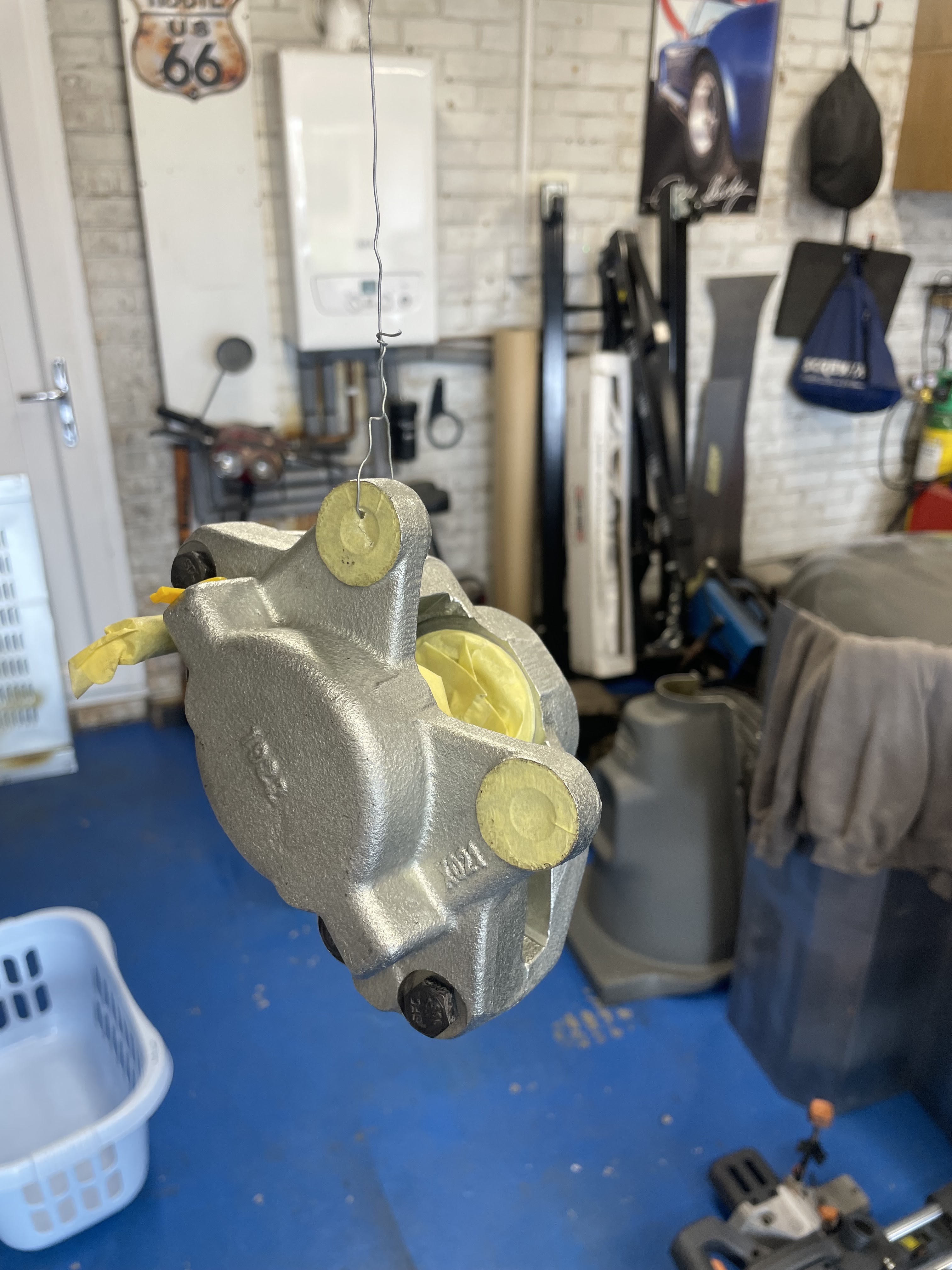
So now the chassis rolls it’s time to get it to stop rolling. I splurged a little cash on a front brake kit with some upgraded rotors as they are drilled and grooved to help with a little heat dissipation. First up really was to make the callipers cosmetically nicer, so the seals were popped out and masked up the areas that need to stay paint free. I gave them both a good degrease first as I want the paint to stay bonded to them as despite them being a nice galvanised finish it needs a good etch on top to bite into the surface and then for the paint. I took my time doing all this and did one calliper one day then the second calliper the day after then a top coat finish that will match the body of the car when finished, a luscious Ferrari Rosso Corsa red. I haven’t owned a red car for many years and whilst it’s a very bright colour it will look tremendous on this project when finished, and matching callipers is all in the grand plan with the attention to detail.


With the callipers painted and left to cure for a day it was time to start getting everything assembled and making sure it was going to fit ok. I started off fabricating some brackets that fix on to the top wishbone bolt that are the fixing point for the brake flexi to the ridged copper brake pipe. I spent flipping hours fabricating these little bits of bent steel cutting, filing, drilling and bending them both perfectly. Then I spent time etching them and painting them to match the chassis….. then to cut a long story short as soon as I had finished them and was really happy with how they had turned out, I went and found the original brackets in my box of bits that I have saved from the strip down…. Bugger. 
I then reverted back to the original’s after a good wire brush clean, etch prime and paint again. The originals are much more beefy the ones I made as I only had some 18gauge steel as opposed to these that are double bonded 3mm steel so really strong in comparison to mine….. belt and braces.


Not all is in vain with my now redundant brackets as they will come in useful for the bell housing bolts as they can act as a clip point where the brake line passes over the transmission to the servo so I’ve really just solved a problem way further down the line, way before I get to it. 

I moved onto the front hubs next and spent some time wire brushing and removing all the texture paint from the back of the hub to give a good machined face surface for the brake rotor to sit against. The rotors fitted perfect to the hubs and were torqued up to, in my opinion, a relatively low 88Nm and now with the rotors on the hubs the whole assembly went back onto the stub axles. I’m not setting all the bearings under load yet as they will be on and off many times again over the next few months during the build so just on finger tight for now.


 In went the brake pads that came in the kit, mixed reviews on these over the internet and the social media groups, still they will be fine for my needs and it’s not like brake pads are expensive or hard to replace later on if needed. The offside is significantly tighter than the near side on the pads, and keeping in mind no pressure or fluid is present yet it seems like the offside rotor is tad further offset on the calliper centre line. This could be down to the bearings not seating perfectly until they get some use or possibly just tight from being new. I’ll look into possibly adding a shim between the rotor and hub to bring it back or possibly one to watch after the first few miles on the clock after everything has settled in. These are fixed callipers and not sliding so the rotors should be fairly central in the calliper to avoid uneven pad wear over time.. a little niggle but “should” be easy enough to sort out.


I’m really pleased with how these are looking and will hopefully be pleased with how they perform also. They must be the smallest brakes I’ve ever seen in my life, but should be more than sufficient for my little Spyder. After all they will be doing less of a job then if a Spitfire body was going back on. 

Next up I think I need to tackle the steering rack. I have watched some really good videos on you tube on a full refurb which had easily given me the confidence to tackle it myself.  I will enjoy the strip down of that and cleaning it all up. I’ll need to order the standard perishable parts but other than that it should be straightforward to do and enjoyable… it’s nice to finally start building and putting stuff together again, very satisfying. 


Sunday, July 9, 2023

Rolling Once Again!

 So I’ve been having some issues with the fitment of the front hubs, specifically the bearings and stub axles. My last post showed how the outer bearing was a terrible fit on the stub axle. So bad I ended up returning the full bearing kits and replacing the new stub axles completely also. My replacement parts are much better fitting than the last ones, but I have still had to have a fair old fettle to get them to fit nicely and allow the bearing to fit correctly as they should. These replacements parts are sure as hell not built to the same tolerances as the original unit which makes things very frustrating to build up again. 

With switching the stubs and bearings I have gone from an impossible fitting outer bearing and good inner to a bad fit inner bearing, but the outer was good. In order to remedy the fit I have basically emery cloth the hell out of the stub after firstly using some various grades of wet and dry to reduce the overall diameter, this has been laborious to do but now the inner and outer bearings fit perfectly…. Phew! and more importantly they will now operate as intended with the specific end float and bearing adjustable as wear slowly happens. The bearing races were driven in using the bearing drift set I got many years ago, this ensures the race sits even and square in the hub, with zero damage to the face which can happen if using a punch to sit them in. Any damage to the race face will reduce the lifespan of the bearing significantly so these are a great tool to have in the garage. 

I also picked up some water deflectors for the front hubs, these are not available anymore as a replacement part so secondhand is the only option, I only had one when I got the car, but picked up a pair for £10 off eBay. I’ve wire brushed them back and then primed and painted them also. Some feedback on the forums is that they are not really required, however they were designed to be on the car so they are staying on mine…. They serve a purpose after all and my front wheels will be significantly more exposed to the weather then on the original Spitfire, so on they went with copious amounts of waterproof grease in the hubs and bearings. 
 With both sides done I was able to offer the hubs up and make sure I had no problems, I torqued up the stub axle nut (88Nm) and solved the previous issue where the steering arm wasn’t sitting correctly…. I had a washer between the hub upright and steering arm which was spacing it out unnecessarily. This was down to not remembering how I disassembled it all and trusting the schematics that you find online listing all the component parts with relevant part numbers….Shock eh, the internet having the wrong information everywhere. 

On went the old original wheels and were rolling again, great!!  Granted the wheels toe out whenever you push it, as no steering rack is on yet (need to start refurbishing this now) and also no front or back brakes either. I have all the brake components in my online basket, and the intention was to have all these fitted now at the same time for this update. However with all the tolerance issues I’ve been having I’m trying to broaden my supplier list and find someone who provides machined parts that actually fit correctly. So I’m holding back for the moment until I’m confident that the parts I order will be ok. 


So that’s it really for this update, short and sweet. I have lifted the body onto the now rolling chassis and must admit it’s looking bloody fantastic and very exciting. I will be ordering the final stage parts for the chassis in the next few weeks and so another little update should happen soon. I’m considering upgrading the front brakes discs and callipers to some vented units that are “supposedly” an improvement, however on a car that has no servo assist and will be significantly lighter than the original I really need to weigh up the pros and cons of making changes to the standard setup. 


Friday, June 2, 2023

It’s Building Time!!

As soon as the paint was dry and the chassis back in the garage it was time to start the build up of the suspension and axles. I started off fitting the differential and rear leaf spring which mount solid to the chassis and I’m using the original bushes here, they are really good condition and are virtually as new. The spring as you may know from previous blog instalments has been fully re-tempered/hardened and I have fitted some heavy duty poly bushings and leaf buttons to help with any sagg, this will not really become apparent until the full weight of the car is sitting on the ground and with my fat bum also in it. 

Next I moved to the front suspension and fitted all the new poly bushes to the upper and lower arms, I opted for the “comfort” version poly bush as opposed to “solid/hard” I want to really clock up some miles in this machine when finished and I don’t want to feel every bump through my spine really, and the comfort bush is still considerably harder than the original rubber units…
 
I then moved onto the front hubs and stub axles. My original stubs were far from acceptable when stripped down and were unable to be reused so replacement units had to be purchased. I had been reading up on replacement units being a poor fit and poor tolerance against the original units, but I presumed that buying replacement parts from reputable suppliers (Rimmer Bros in this case) that these issues would not effect me….. I was wrong. 

I pressed the new bearing races into the hub and all was going well during a dry fit prior to any grease and the first problem surfaced when trying to fit the outer taper bearing. The outer face of the sub axle has not been machined to the same diameter as the original which stops the outer bearing sliding onto the axle as it is too big in diameter. The bearing is essential to fit correctly here as you control the tension on the bearing using the castle hub nut and split pin…. Too tight and your wear the bearing out quickly, too loose and you risk damaging the stub itself and bearing failure and hub damage. This has really pissed me off to be fair as these were not really cheap replacements from Rimmers and they shouldn’t really be allowed to sell something that is not fit for purpose, however I will have a conversation with them after the bank holiday and see what resolution they are going to offer.

It is definitely the stub at fault here as opposed to the wrong bearing, as the replacement bearing fits perfectly on my old knacked axel stub, so that has stopped me going much further with the front end. I continued to fit the upper wishbones and front coil spring and shock, however until a perfect fit can be achieved for the front hubs I can’t continue with anything like the front brake assembly…. Bugger. 

If I continue to get crap parts in regards to these stubs I’ll have to consider a machine shop to turn the outer diameter down slightly in order to get the bearing to fit. Once done correctly they “should” outlive the rest of the car to be fair, so I’m keen to get things like this correct from the start… I’m sure as hell not going to start making compromises with components like this. 


So moving to the back end then… should be fairly straightforward….. should. First off was to put the new universal joints in. This is a straightforward job with aid of the bench vice, I have done these before with the Cobra build but was considerably more challenging when having to knock them in with a socket and hammer. So it was enjoyable to simply press them in with the vice and set the circlips in. Then I fitted the lower rear trunion bush, these are made up of sleeved poly bush with dust ring and covers. They are a bloody tight fit in the hub vertical upright and a considerable amount of swearing took place before they were fully fitted, however once fitted together it was easy to then fit the half shaft to the diff and ready to fit the shock absorber. 

The slight challenge to the rear end is the amount of tension everything is under to get all these bits back together without any serious load (no body, engine or gearbox weight) but with some logical thinking and use of a trolly jack and farm jack I managed to get everything aligned and fixed ready to make a start on the rear adjustable radius arms. 

I still need to overhaul the rear brakes but I whacked on the old wheels to see what suspension travel I had when sat on the floor and to gauge some overall width etc… fairly pleased with how this is starting to come together and definitely another step forward has been made.

Next on the list is to start on some mechanical components and to get the front and rear brakes trial fitted. I still need to order all these bits but these “should” be fairly straightforward and enjoyable to fit without too much head scratching. 
I do have to figure out what is wrong with the steering arm on the front hubs still, as despite putting it back together as instructed through the Haynes manual and various online diagrams I’m getting a issue when the offset face will not align. 

I’m simply either missing a spacer washer or it could be the brake heat/dust shield, that is the issue. I can’t recall exactly when I stripped it all apart, but until I can get the stub axel sorted for the bearings to seat properly then I have some time to figure out what is wrong. 

So everything is starting to come together fairly well, classic case when building cars of two steps forward, one step back. I’m going to have to start saving for some knock on hubs wheels and tyres or start searching for some second hand units through forums and eBay. I also will need to fire up the mig again to fix the rear radius arm plates…. Joy!! More grinding and making dust everywhere!,


Tuesday, May 23, 2023

More Paint than Bob Ross


Welcome back along, not a massive leap in progress here I’m afraid but the final paint finish for the chassis and this means I can start to build it all up now and get it rolling…. Phew, it’s getting heavy!

Over the past few weeks the weather has definitely turned and the second weekend of the month saw the thermometer showing a giddy 18 degrees, so out came the chassis from the garage and a good clean down, degrease and etch prime ready for more texture top coat. I learnt my lesson last time and have put down poly sheet all over the floor to protect the slabs slightly as the fall out last time got a tad messy and sticky. But this time it’s just a dusting of etch primer so shouldn’t be too bad, but prevention is better than cure and it was much easier to tidy up this time around. 

I started off by just scotch pad scuffing the chassis bare metal all over and a good degrease to remove anything that could potentially stop the primer from biting in to the metal and stopping the bond. I won’t be hitting with the black texture top coat until a week after to allow the primer to fully cure and less risk of any reaction. 

The first coat of primer went on well and has covered nicely, fair to say it uniformed everything and makes it look much better. So after an hour or so to tac off I flipped the chassis over and hit the underside of the floor pan also. 


Again it didn’t take me long to lash the underside with the primer also, and after another few hours I had got the chassis back in the garage waiting a week for the final finish. During this time I have also sealed all the panels with seam sealer.
The seam sealer does exactly what it says and will seal the panel join to protect it from corrosion and moisture. I have sealed all the internal and external seams along with the sills on either side. This “should” help reduce the risk of water ingress and corrosion setting in so it’s a preventative measure really, however it does neaten off all the seams and makes them look much better. The underside of the chassis now looks really good and the sealer between the chassis and floor pans just looks right as well as practical.

Next up is to get hitting it all with some topcoat. Same stuff as last time before I welded on the new floor pans and out riggers. It’s a 2k product called Gladiator bed liner (Raptor alternative) Its extremely hard wearing and gives the desired texture finish that I want. I deviate slightly from what everyone else does with this product and thinned it slightly to put a base coat down with a 1.7 gravity gun. Then after 20/30 minutes to tac a little I then hit it with the schutz gun to give the texture finish. I’m treating all the running gear to the same finish as the chassis, so when finished then the final product will hopefully look fairly uniform and consistent throughout. Once this was all done the chassis is ready to start taking some rebuilt running gear and a start on getting this project rolling.


I learnt my lesson off last time when I applied some paint and I have covered the floor with protective sheet, the fall out literally goes everywhere and is sticky as sh*t but all went well and the chassis was soon done. I erected my pop up gazebo again and used that to hang all the running gear components from with old rusty mig wire which allowed me to get a good coverage on all parts, and then it was just to leave it all to harden and cure…. Which didn’t take long with the weather being so good currently.


So fully painted chassis is back in the garage and is looking great, it will be a shame to cover it all up never to be seen again upon the rebuild. However the next update should be fairly soon as I had a delivery of nuts, bolts and bushes a few weeks back so I’m ready to start the next step straight away really.